PARTSTOBEINSTALLED
NOTE: Be careful not to lose the caged nut located
in the bottom fixation hole of the front cargo mod-
ule.
5. Open front storage compartment cover.
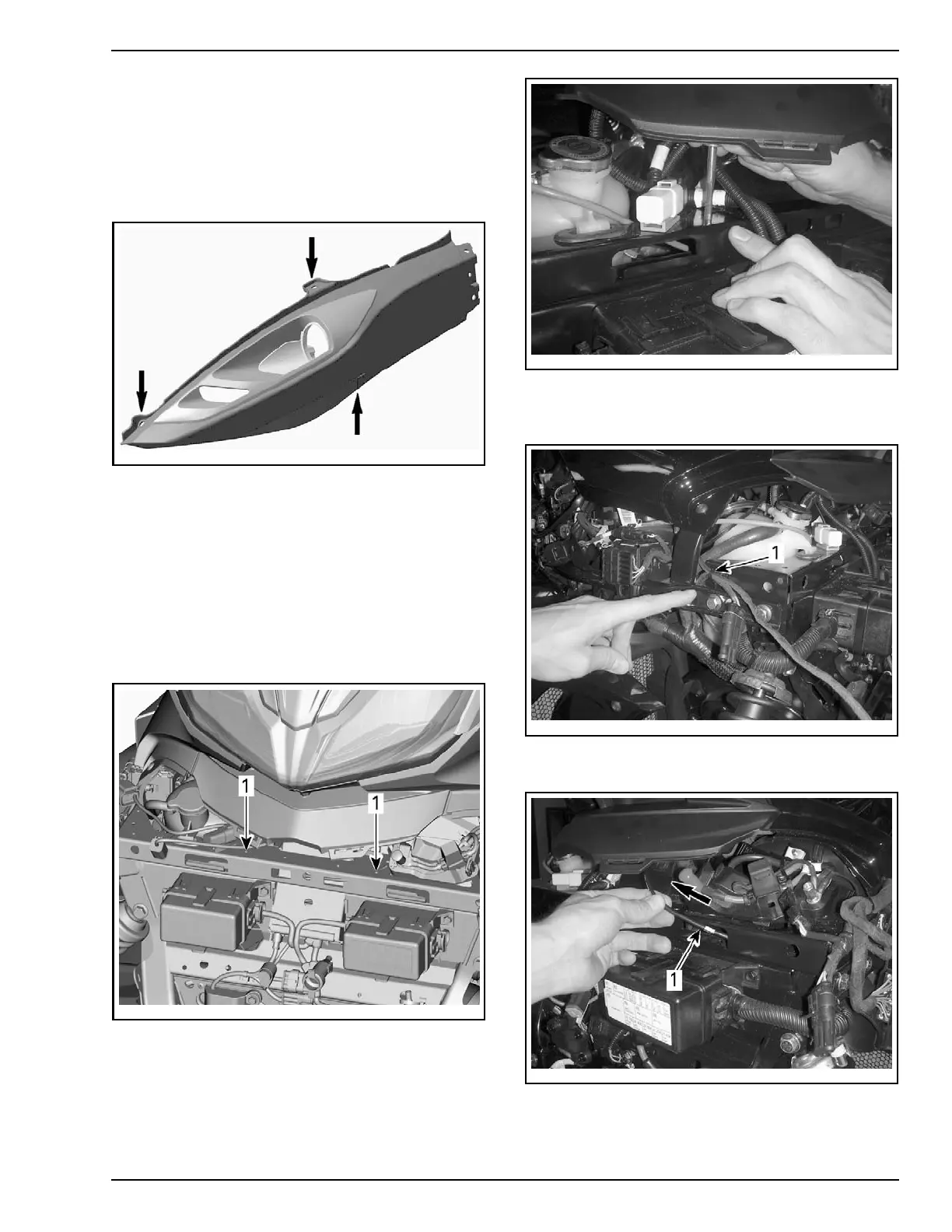
6. Remove 3 plastic rivets securing LH and RH
front panels.
rbl2008-003-100_d
TYPICAL - FRONT PANEL PLASTIC RIVET LOCATIONS
7. Cut locki
ng ties securing horn and AAPTS har-
ness to fr
ame.
8. Tap two middle holes on the vehicle frame for
M6 x 20 screws (from PDI kit).
NOTE: Running a tap through the two middle
holes is not necessary since the M6 X 20 screws
provided in the PDI kit are self-tapping screws.
However, it will ease installation of the middle
screws due to screw hole access constraints.
rbl2013-003-022_a
1. Holes to tap for scr ews
rbl2013-003-018
TYPICAL
9. On RH side, undo reusable locking ties and se-
cure harness as shown.
rbl2013-003-019_a
1. Tie rap
10. Extract hood latch release cable.
rbl2
013-003-020_a
1. Hood latch release cable
PREDELIVERY 2014-3 13 / 41
 Loading...