4. Operation With ADC and MCA
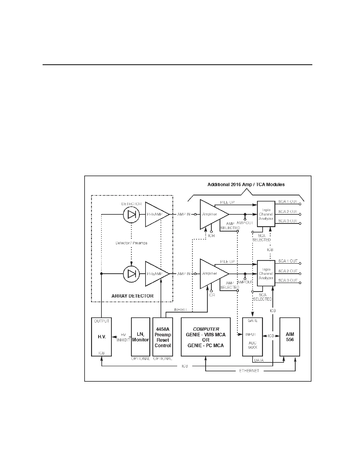
Figure 5 shows a typical array detector system configured for 2016 Amplifier/TCA
calibration and operation. Each Preamp output is connected to a 2016 Amp Input. SCA
parameters are computer controlled through the Model 556 AIM, utilizing Canberra’s
Instrument Control Bus (ICB). All 2016 Selected SCA Outputs are connected to an
ADC Gate Input. The 2016 Selected Amp Output is connected to an ADC Input. With
the ADC configured for Delayed Peak Detect, the 2016 Selected SCA controls ADC
conversion, allowing calibration of each 2016 Amplifier/TCA. When calibrating each
2016 Amplifier/TCA module, its SCA energy window is set up and SCA count analy
-
sis can begin.
10
Operation With ADC and MCA
Figure 5 Typical 13-Element Array Detector System