CANNON Instrument Company | Unpack & Assemble
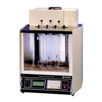
Figure 12: Remove Heater Housing
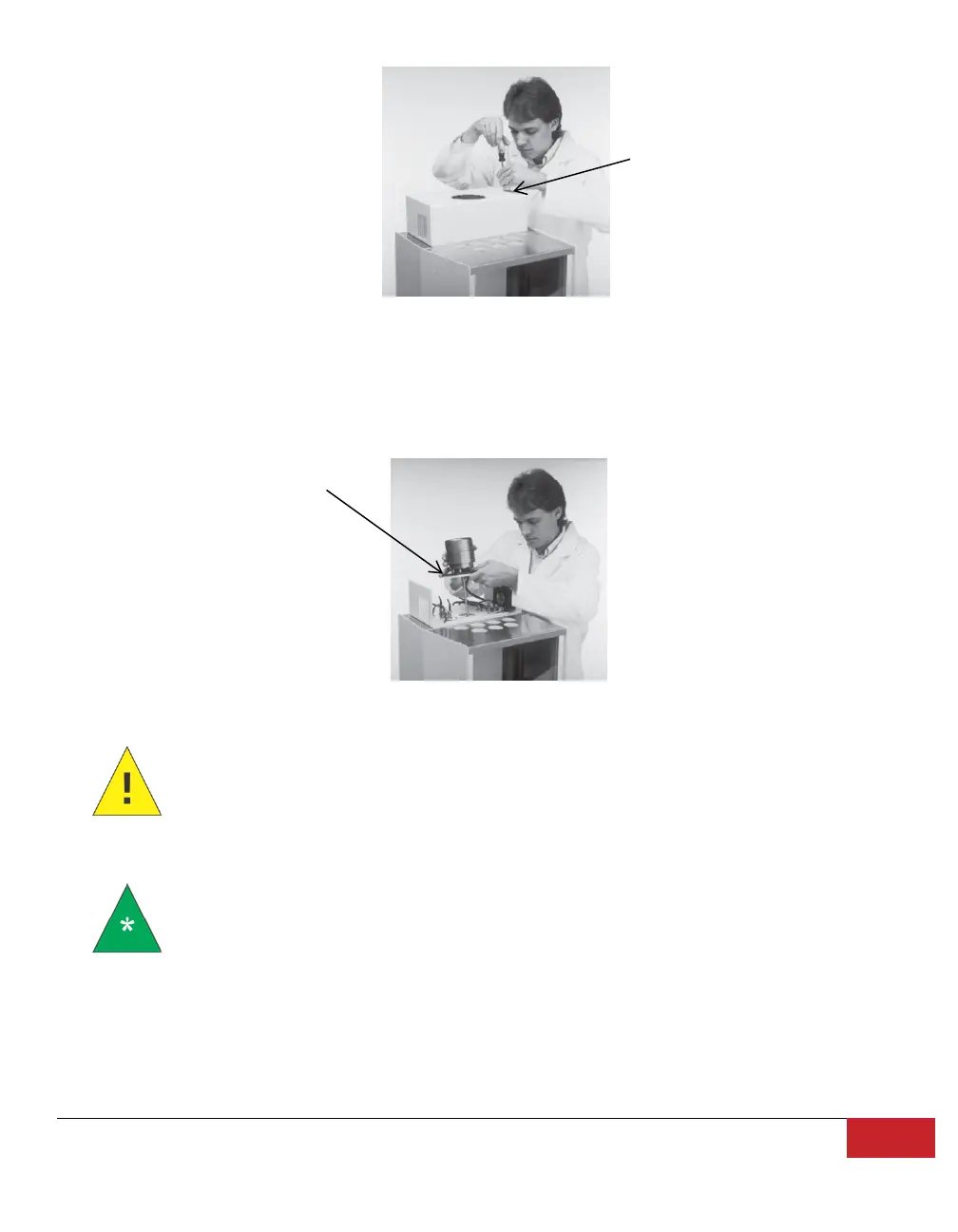
16. Check the motor-stirrer impeller blades to make sure that the flat sections all lie along the same
plane (see Appendix I: Correcting Shaft & Impeller Misalignment), then insert the motor-stirrer
into the opening provided, as shown in Figure 13.
Figure 13: Install Motor-Stirrer
Caution: Avoid accidental bending of the motor shaft by NOT holding the motor
assembly by the shaft. Use care when inerting the motor shaft and impeller to
prevent damage to delicate components.
Note: Two screws located on either side of the opening serve as the locating pins
for the motor support pad. Do not remove these screws as the holes in the pad fit
loosely over their heads. The motor line cord should point towards the rear of the
bath (offset slightly to the right or left). The motor-stirrer should now lie flat on
the top of the bath.
17. Connect all plugs and probes to the correspondingly labeled sockets at the rear of the CT-2000
bath unit as shown in Figure 14 and in the following list.
Removing two screws
Insert motor-stirrer
into opening