12 • Introduction
Names of buttons and switches other than the
joystick are indicated within a
“button” frame
(for example ).
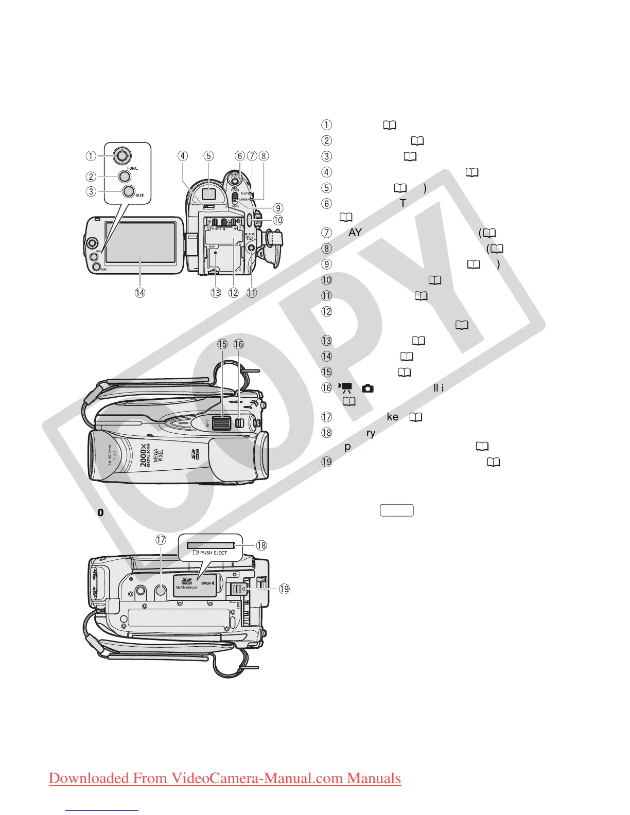
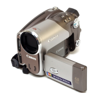
Back view
Top view
Bottom view
Joystick ( 18)
FUNC. button ( 19, 60)
DISP. button ( 33, 55)
Dioptric adjustment lever ( 27)
Viewfinder ( 27)
QUICK START button and standby lamp
( 29)
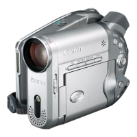
PLAY mode indicator (green) ( 18)
CAMERA mode indicator (red) ( 18)
OPEN (disc cover) switch ( 23)
Start/Stop button ( 26)
DC IN terminal ( 17)
Serial number/
Battery attachment unit (
16
)
RESET button ( 67)
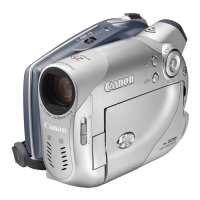
LCD screen ( 22)
Zoom lever ( 28)
/ (movies/still images) switch
( 18)
Tripod socket ( 17)
Memory card slot
(open the cover to access) (
25
)
BATT. (battery release) switch ( 16)
FUNC.
COPY
Downloaded From VideoCamera-Manual.com Manuals