Do you have a question about the Canon DC10 E and is the answer not in the manual?
Details the design philosophy including slim styling, DVD player compatibility, and high image quality.
Lists key features such as high image quality and advanced functions for comfortable operation.
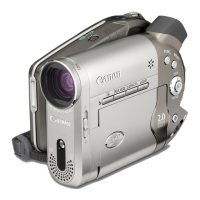
Illustrates the external appearance of the DC20 E, noting differences from the DC10 E model.
Explains the design concepts, focusing on circle grip styling for operability and rounded rear shape.
Provides an overview of the TS Mech, a DVD drive for DVD cameras, detailing its dimensions and specifications.
Details the main mechanical components of the TS Mech, including spindle motor, control board, and pick-up assembly.
Specifies the camera type, DVD recording modes (movie, still image), and recordable disc types.
Details the continuous battery shooting time for various recording modes and settings.
Illustrates the interconnection of all major components and PCBs within the camcorder system.
Presents block diagrams for various camera sections, detailing signal flows and component connections.
Provides block diagrams for the system control section, illustrating its interaction with other units.
Presents block diagrams for the audio-video section, showing signal paths for audio and video.
Details the power supply section's block diagram, showing power distribution and regulation circuits.
Illustrates block diagrams for Flash PCB, LCD PCB, CARD/LI, DC JACK PCB, and FPC sections.
Lists essential maintenance tools required for service and adjustment procedures.
Details how to use the extension connector and set up the device for service mode operations.
Explains how to enter service mode, operate the remote controller, and understand indications.
Describes various service modes including error rate, camera commands, and key/switch checks.
Outlines adjustments required after replacing major components like CCD, AF, IS, and camera sections.
Details CCD image adjustment steps, including temperature checks, iris, and image adjustments.
Covers AF adjustments (VCM, CZ, Cam Correction) and IS section adjustments (Gyro Offset, Data Writing).
Details adjustments for camera (Iris, WB, Color Balance) and recorder sections (error rate checks).
Provides procedures for CVF adjustments including forced ON, frequency, COM-DC level, amplitude, and brightness.
Shows the arrangement of circuit boards and the location of main electronic elements.
Provides specified current consumption values for various operating states of the camera.
Guides on detecting power supply malfunctions, checking keys, communication, and fuses.
Outlines checks for camera picture issues, including lens reset, index screen, and DIGIC DV signals.
Provides flowcharts and methods for checking playback picture malfunctions related to discs and error rates.
Details cautions for handling the TS Mech unit, including antistatic protection and laser beam safety.
Provides instructions on how to remove and dispose of the built-in lithium battery safely.
Lists and explains various warning displays and error messages encountered during operation.
Illustrates the interconnection of all major components and PCBs within the camcorder system.
Presents block diagrams for various camera sections, detailing signal flows and component connections.
Provides block diagrams for system control and audio-video sections, showing signal paths.
Details block diagrams for power supply, Flash PCB, LCD PCB, CARD/LI, DC JACK PCB, and FPC sections.
| Camcorder Type | Digital Camcorder |
|---|---|
| Digital Zoom | 200x |
| Optical Zoom | 10x |
| Focus Adjustment | Automatic, manual |
| Shooting Modes | Auto, Manual |
| Image Stabilizer | Electronic |
| Display Type | LCD |
| Connector Type | USB, AV |
| Battery Type | Lithium-Ion |
| Recording Media | MiniDV |
| Display Size | 2.5" |
| Viewfinder | Color |
| Microphone | Built-in |