Chapter 2
2-1
2.1 Basic Construction
2.1.1 Outline
0010-4342
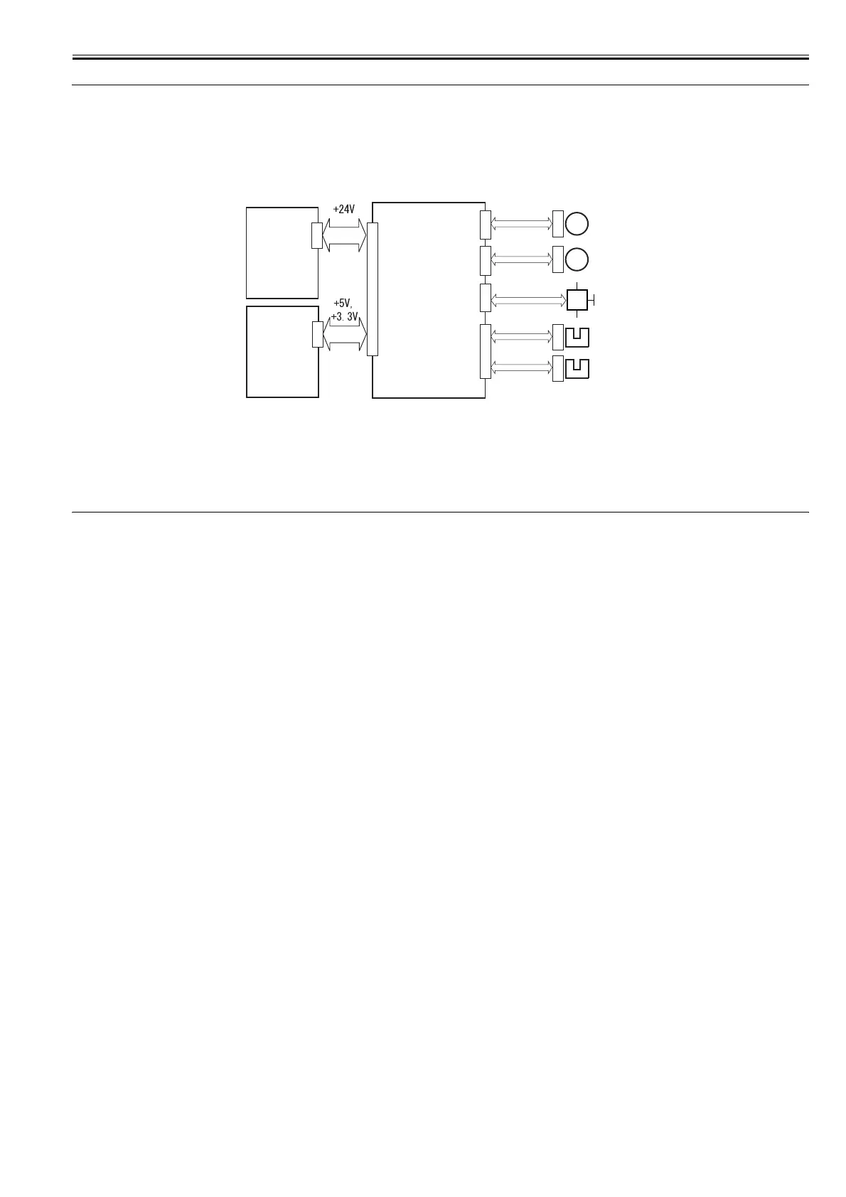
The operation sequence of the duplex unit is controlled by the duplex controller PCB. An 8-bit microcomputer mounted on the duplex controller PCB controls the
operation sequence of the duplex unit and the serial communication with the DC controller PCB.
The duplex controller PCB drives motors in response to various commands sent from the DC controller PCB. The DC controller PCB sends the duplex unit status
back to the printer. The duplex unit is powered by 24 VDC supplied from the power supply kit PCB and +5VDC and +3.3 VDC supplied from the DC controller
PCB.
The duplex unit circuit configuration is shown below.
F-2-1
T-2-1
2.2 Pick-Up/Feed Systm
2.2.1 Outline
0010-4343
After the printing paper is fed by the delivery roller in the fixing unit of the host machine, the duplex flapper solenoid (SL1001) turns on to lead the paper to the
duplex unit.
The printing paper led to the duplex unit is fed by three feed rollers to the printer.
The reversal motor (M102) and feed motor (M1001) are stepping motors. The rotation direction of these motors is controlled by the microcomputer (CPU) mounted
on the duplex controller PCB.
Feed roller 1 is driven by the reversal motor (M1002). Feed rollers 2 and 3 are driven by the feed motor (M1001). The paper transport path is provided with two
photo interrupters, duplex paper sensor 1 (SR1002) and duplex paper sensor 2 (SR1003).
M1001 Feed motor SR1002 Duplex paper sensor 1
M1002 Reversal motor SR1003 Duplex paper sensor 2
SL1001 Duplex flapper solenoid
DC
controller
PCB
J1002
J218
M1001
M
J275
J1005
M1002
M
J276
J1006
SR1002
J273
J1003
SL1001
SR1003
J274
SL
Optional
power
supply
PCB
J1001
J55