B. Analog Image Processing
1. Outline
The analog processor PCB converts CCD drive signals and CCD output signals (analog signals) to dig-
ital signals. (It also executes AE measurement.)
2. CCD/CCD Driver
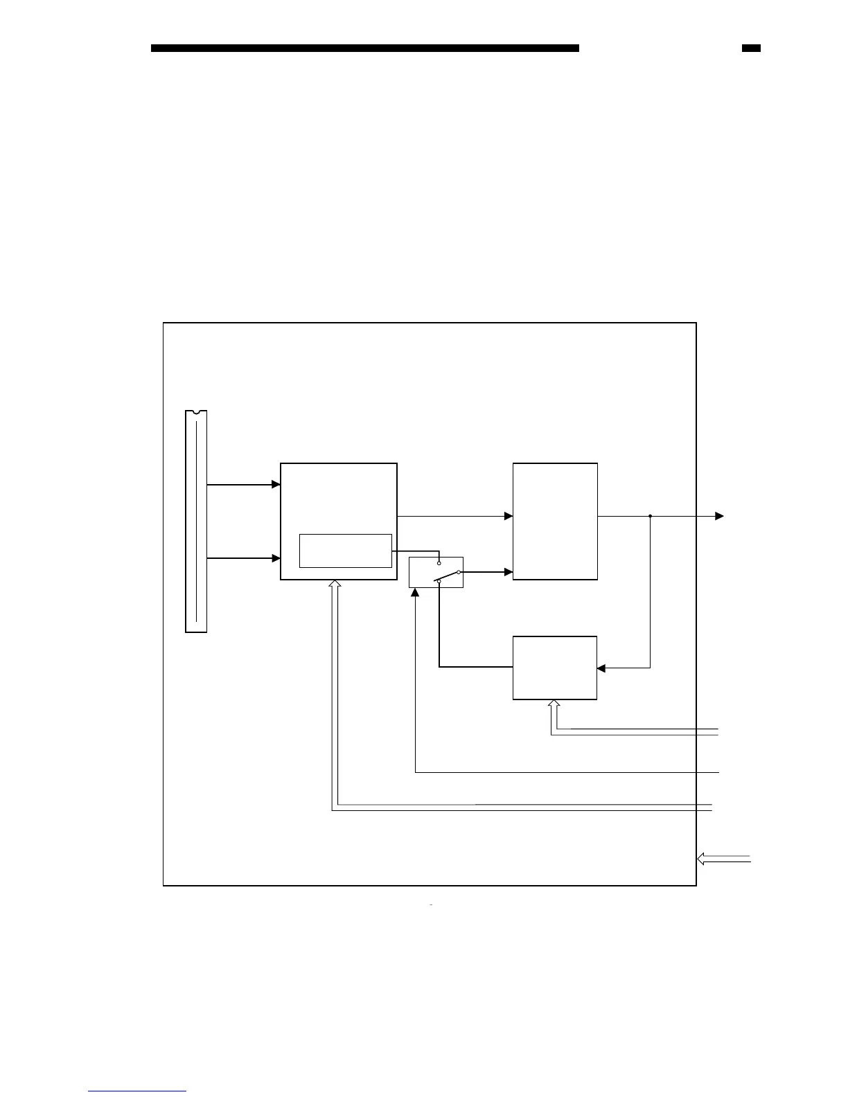
The GP215/GP200’s CCD is a linear image sensor consisting of a single line of 7500 photocells. The
signals subjected to photoelectric conversion in the photocell unit are forwarded to the CCD drive circuit.
(The even-number pixels and the odd-number pixels are sent separately.) The CCD drive circuit synthe-
sizes the signals coming separately in even-number units and odd-number units for output to the A-D con-
version circuit.
Figure 3-302



 To Next Page