12
General notes:
- Make sure that the flexible cables and wires in the harness are in the proper position and
connected correctly.
- Do not drop the ferrite core, which may cause damage.
- Protect electrical parts from damage due to static electricity.
- Before removing a unit, after removing the power cord, allow the printer to sit for approx. 1
minute (for capacitor discharging to protect the logic board ass'y from damages).
- Do not touch the timing slit strip film and timing slit disk film. No grease or abrasion is allowed.
- Protect the units from soiled with ink.
- Protect the housing from scratches.
- Exercise caution with the red screws, as follows:
i. The red screws of the paper feed motor may be loosened only at replacement of the paper
feed motor unit (DO NOT loosen them in other cases).
ii. DO NOT loosen the red screws on both sides of the main chassis, securing the carriage shaft
positioning (they are not adjustable in servicing).
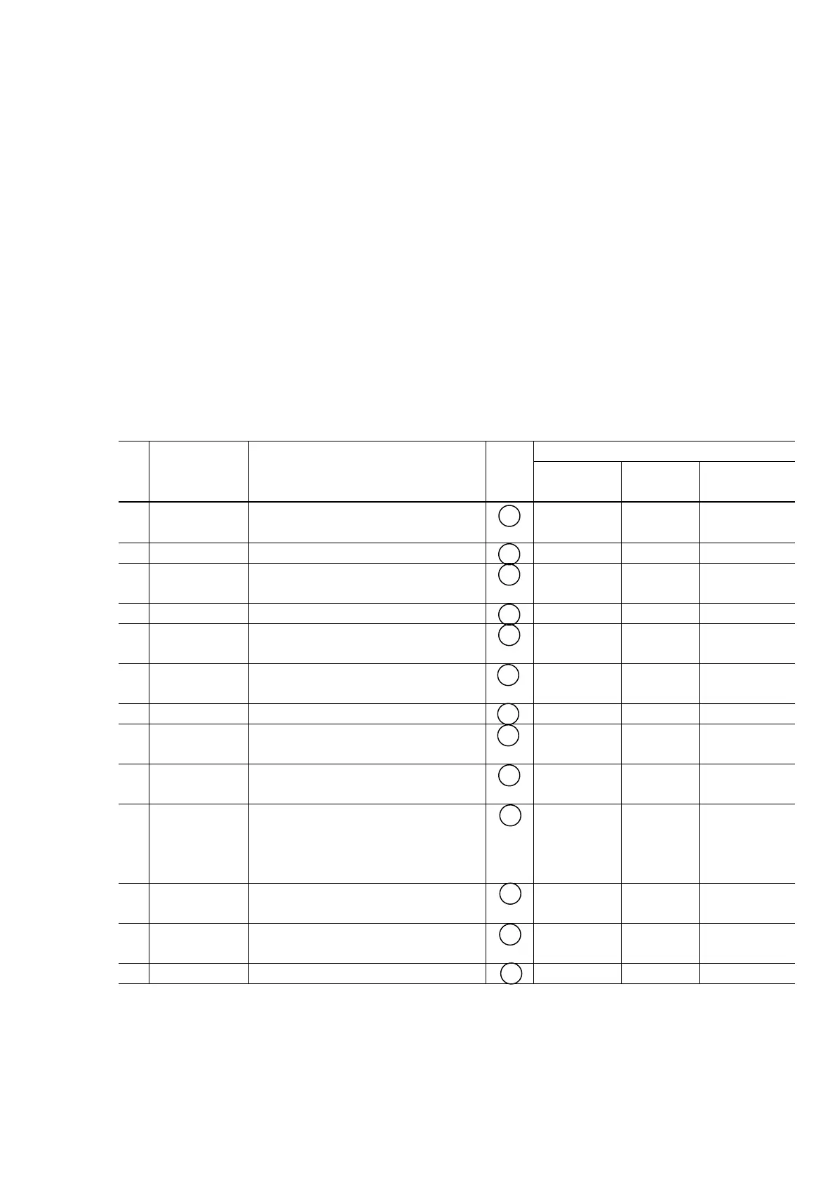
4-2. Grease Application
(1) Printer unit
Grease / oil
No. Part name Where to apply grease / oil
Picture
No.
Name
Amount
(mg)
Number of
drops*
1 Chassis ass'y Entire surface the carriage slider
contacts
1 Floil KG107A 27 to 54 3 at 1 location
2 Adjust plate L Carriage shaft cam L sliding portion 2 Floil KG107A 18 to 36 2 at 1 location
3 Chassis ass'y Carriage shaft sliding portion on the
left side of the chassis (at 1 location)
3 Floil KG107A 9 to 18 1 at 1 location
4 Adjust plate R Carriage shaft cam R sliding portion 4 Floil KG107A 18 to 36 2 at 1 location
5 Chassis ass'y Carriage shaft sliding portion on the
right side of the chassis (at 1 location)
5 Floil KG107A 9 to 18 1 at 1 location
6 Chassis ass'y PR lift shaft cam contact portion (at 3
locations)
6 Floil KG107A 18 to 27 1.5 each
at 3 locations
7 Idler pulley Idler pulley hole contact portion 7 Floil KG107A 9 to 18 1 at 1 location
8 Carriage shaft Entire surface of the carriage shaft
where the carriage unit slides
8 Floil KG107A 200 to 400
9 Carriage shaft
spring L
Carriage shaft sliding portion (to the
end of the spring)
9 Floil KG107A 9 to 18 1 at 1 location
10 Carriage shaft Carriage shaft surface where the
carriage slides (and where
machine-application of the grease is
not feasible)
10 Floil KG107A 9 to 18 1 at 1 location
11 CL gear base Outer surface of the CL idle gear R
cylinder
11 Floil KG107A 9 to 18 1 at 1 location
12 CL gear base Outer surface of the CL output gear
cylinder
12 Floil KG107A 9 to 18 1 at 1 location
13 CL input gear Joint of the CL gear base 13 Floil KG107A 9 to 18 1 at 1 location
* 1 drop = 9 to 18 mg