CHAPTER 8 EXTERNALS AND AUXILIARY CONTROL SYSTEM
COPYRIGHT
©
2002 CANON INC. 2000 CANON iR1600/iR2000 REV.1 JAN. 2002
8-25
6.5.3 Removing the Image Processor PCB
1) If you have replaced the PCB, go
through the instructions given for re-
placement (See to 2.3.4 in Chapter13).
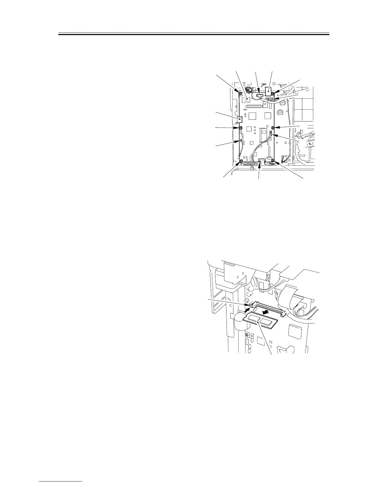
2) Remove the rear cover.
3) Disconnect all connectors and the flex-
ible cable [1] from the image processor
PCB.
4) Remove the 6 screws [2], and detach the
image processor PCB [3].
5) If you have replaced the PCB, go
through the instructions given for re-
placement (See to 2.3.4 in Chapter13).
F08-605-03
6.5.4 When Replacing the Image Processor PCB
Go through the steps given for the replacement of the image processor in 2.3.4 of Chapter 13.
6.5.5 Removing the RAM DIMM
1) Taking care not to touch the elements,
push down the socket lever [1], and de-
tach the RAM DIMM [2].
F08-605-04
[1]
[2]
[1][3]
[2]
[1]
[2]
[1]
[1]
[2]
[2]
[2]
[1]
[1]
[1]
[2]

 Loading...


