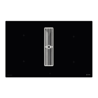
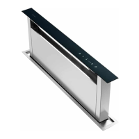
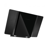
Instruction manual DD810BK
50
Please keep this instruction manual for future reference
› The product may only be connected by a qualified fitter according to applicable
local regulations. The same applies for the extraction air connections. The fitter is responsible
for proper functioning at the installation site.
› On installation, observe the relevant national building regulations and the regulations of the
electricity suppliers.
› The hob fan can be operated in the extraction air and recirculation air mode.
› Lead the extracted air outside through a ventilation shaft intended for this purpose or
through the wall of the building.
› Extracted air may not be led into a smoke or exhaust gas flue which is in operation.
› A sufficient supply of inlet air must be provided if a wood, coal, gas or oil heater requiring
a chimney is operated in the environment of the hob fan, since an insufficient supply of air
results in a risk of poisoning. The safe operation of the hob extractor is guaranteed when the
negative pressure resulting from the hob extractor does not exceed 0.04mbar (4 Pa) and a
sufficient supply of inlet air can flow into the room.
› Exhaust air pipes must comply with fire class B 1 DIN 4102.
› Please make sure that the mini mum nominal width of the appliance connecting pieces is
not reduced.
› A system recommended for the airflow and compatible with the hob extractor should always
be used.
› The nominal width of the recirculation air pipe should not be less than 150mm.
› Exhaust air pipes should be as short as possible. They should not have a 90-degree angle;
instead they should have soft bends and no reductions in their cross-section.
› Never use pipes with a diameter of less than 150mm. No bends/angles may be laid 50cm
before the fan module
› Always insert a straight piece of approx. 50cm between two angles/bends.
› The cross-section of wall vents and the cut-out in the base panel should should at least
correspond to the exhaust air pipe. The outflow opening must be at least 500cm². Reduce
the height of the skirting boards or make corresponding openings.
› When installing the appliance make sure that the convection air unit is still accessible when
the kitchen has been completely installed.
› If necessary, levelling feet for the kitchen units must be moved.
NOTE:
When the convection air mode is in operation, ventilation must be sufficient in order for
the air humidity to be removed.
EXPLANATION FOR SYMBOLS AND INDICATIONS
This appliance was produced according to state of the art technology. Machines nevertheless give rise to risks which cannot be
constructively avoided.
In order to guarantee sufficient safety for use, safety instructions are also given. These instructions are marked by way of the
highlighted texts which follow.
Sufficient safety in operation will only be guaranteed when these instructions are observed.
The designated text passages have different meanings:
NOTE
Note to be observed in order to make handling the appliance easier.
WARNING OF ELECTRICAL ENERGY RISK OF FATAL INJURY
Live components have been installed near this symbol. Covers bearing this sign may only be removed by a
certified skilled electrician.
 Loading...