GBGB
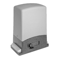
FIXING THE GEARMOTOR AND RACK
Decide the position of the motor, depending on whether the installation is right-hand (R) or left-hand (L).
Allow a minimum gap between the base of the motor and the end of the rack. In right-hand (R) installations, the motor must be
retracted by at least 20 mm to allow the magnetic limit switch to be fitted.
Before fixing the plate, make sure that:
- the surface is level and solid enough for effective mounting
- the passage for the electric wiring is on the correct side (fig.D)
- the base is perpendicular to the direction of travel (fig.D)
- the distance from the leaf allows the pinion to be correctly aligned with the rack (fig.D)
- the height allows the pinion and rack to mate correctly
- the gate can be released smoothly (fig.D)
If the supporting base is the right height and solid enough, the plate can be fixed with 4 expansion or chemical anchor bolts.
For new installations that do not have a solid base, the 4 clamps provided can be sunk into the concrete as shown in figure E.
Place the gear motor on the plate and fix the four screws. The slotted holes allow any horizontal adjustments; if necessary, use the 4
stud bolts (detail 6 in figure A) to correct the height and/or to level the motor.
For details on fixing the rack, follow the manufacturer's instructions. We generally recommend:
- the rack must have a M4 module and be specified to support the weight of the gate.
- the joints must not create jolts during gate travel.
- fix a piece of rack temporarily with clamps (fig. F) if it is difficult to achieve an even pitch at the joints.
- some models of rack can be installed with screws, using extra-long holes; in this case, it is useful to subdivide the margin of
adjustment by placing the screws in the middle of the slots.
Warning! We consider correct mating of the rack and pinion as fundamentally important.
They must be as centrally aligned as possible and above all there must always be a minimum clearance to prevent
abnormal loads on the pinion. Release the motor and ensure that the system runs evenly through the entire travel stroke.
If wear on the structure has created sagging which cannot be compensated for easily, the parts should be overhauled.
Once all adjustments and checks are complete, screw down the 4 screws and fit the covers (5).
Important safety notes:
1. The automation system must be installed to good workmanship standards by qualified staff meeting the legal prerequisites and in
accordance with machinery directive 2006/42/EC and the EN13241-1, EN12453 and EN12445 standards.
2. Analyse the risks of the automation system and adopt any appropriate safety and warning measures.
3. Install controls, such as the key-operated selector switch, in such a way that the user is not in a hazard zone.
4. Affix the CE nameplate or label containing the hazard information and ID data of the automation.
5. Consign the instructions for use, safety information and EC declaration of conformity to the final user.
6. Ensure that the user has understood how to operate the automation correctly in automatic, manual and emergency modes.
7. After installation, try out the automation safety, signalling and release devices several times.
8. Inform the user in writing (for example, in the operating instructions):
a. of any residual risks for which no protection is provided, and foreseeable misuse.
b. That the power supply must be disconnected before the gate is released, when performing routine maintenance or during
cleaning of the automation area.
c. That the automation must be inspected frequently for visible damage, notifying the installer at once if any is found
d. That children must not be allowed to play in the immediate vicinity of the automation
e. That the radio remote controls and other control devices must be kept out of the reach of children.
9. A maintenance plan must be provided for the system (at least every 6 months) and the work done recorded in a log.
31 32
MAGNETIC LIMIT SWITCHES (fig. G)
These gearmotors come complete with two brackets with magnets (17 fig. A) and the relative sensor, fitted above the pinion (2 fig. A).
Warning! The two magnets are fitted on the bracket in a position that enables their recognition by the ECU. Dismantling and
swapping the position of either magnet may impair programming and/or operation.
Fit the fixing stud bolts and fit the two brackets temporarily to the opposite ends of the rack (fig. G).
Perform a series of checks with the motor released, moving the gate by hand.
- with the gate closed, the magnet must be facing the sensor
- open the gate and check the same situation with the opening magnet.
- the gap between the magnet and the sensor must not exceed 10mm (fig. H)
- the magnetic limit switch must not be tripped when the gate reaches the mechanical stop; this should occur at least 10 mm earlier.
Do not finally tighten the limit switch brackets; wait for the first operating tests. It may be necessary to correct the positions due to the
motor speed or gate inertia.
Warning! The use of magnetic or electric limit switches is not an alternative to the installation and maintenance of
mechanical limit stops for the gate. These devices must restrict the gate's maximum travel in all situations.
GEAR MOTOR RELEASE AND LOCK PROCEDURE
These two operations are required only in the event of a fault or power failure, and the user or assigned personnel must be
trained by the installer, who should provide a copy of these instructions to be kept with care together with the release key.
Before performing either of these procedures, ensure that the power supply is disconnected from the entire
automation, even in the event of a power failure.
RELEASE: 1) insert the key and turn clockwise 2) pull the lever through approx. 90° 3) the motor is released and the leaf can
be moved manually. To keep the leaf blocked, proceed as follows.
LOCK: 4) close the lever 5) turn the safety key anti-clockwise; the gearmotor is then locked and the leaf can only be moved
electrically.
CONTROL UNIT - DESCRIPTION OF PARTS (fig. I)
1) Terminal board for primary transformer connection
2) Transformer mod. RTRA230V10VACAB1
3) 24 V 0.3 A fuse
4) Terminal board for secondary transformer connection
5) Terminal board for limit switch connection
6) STOP/PROG Pushbutton for Programming and Stop*.
7) P/P Step/Step button
8) Trimmer for motor power adjustment
9) Jumper Jp1 (for motor power cut-out and soft-start)
10) Connector for OC2 series receiver
11) Function dip-switch
12) TEST jumper
13) Encoder connector
14) Terminal board for low tension connections (24V)
15) ECU reset. Shorting the 2 pins for a moment has the
same effect as switching power off then on again.
16) Indicators LEDs for terminal board inputs. LED on =
input closed
17) Programming LED (L1)
18) Connector for Electric Lock Module
19) Terminal board for 230 V connections
20) Terminal board for mains power supply input
21) 6.3 A fuse for line
22) Terminal board for motor and capacitor connection
* This STOP button must never be considered a safety device, but exclusively a service function to facilitate tests
during installation.
ENCODER
The control unit is equipped with an encoder input. This device allows the gate movement to be adjusted with precision and the anti-
crushing protection is guaranteed throughout gate travel, including deceleration.
During the gate travel programming stage, if LED L1 flashes, this means the control unit has detected the presence of the encoder. If,
however, LED L1 remains on constantly, this indicates the control unit will not work correctly with the encoder.
USE OF THE OC2 RECEIVER
The operation and programming of the OC2 series receiver is outlined in the instructions supplied with the receiver.
Please note that the receiver channel 1 always corresponds to the step-by-step (P/P) control on the control unit, while channel 2 is
allocated to the pedestrian control.
PHOTO TEST
For the photo test to work, the system must have two power supply lines for the photocells, the first being connected to terminals 10
and 11, which power the receivers, and the second to terminals 12 and 13, which power the transmitters (the photo test must be
enabled with dip-switch No. 7 in the ON position). The control unit checks the efficiency of the photocells by simulating an activation
at every start of gate movement. If everything is OK the motor starts up, thereby starting the gate movement; if the receiver has any
problems the cycle stops and the open gate light blinks several times to warn of the situation.
- The photo test also works with photocell 2 (Jolly input).
- With the photo test enabled and the control unit in standby, the photocell transmitters are not powered and the FT1 input is open
(LED off). Operation of the photocells may still be checked in this condition by short-circuiting the test jumper (part.12 di Fig 1).
1 2 3
4 5
 Loading...