Radio antenna input
16 Braid
17 Control
Connection only necessary with receiver OC2 active.
Use aerials for frequency 433 MHz (50 Ohm)
Auxiliary device power supply
output
Gate open indicator light
Limit switch closed
Limit switch open
13
14
15
14
20
19 (com)
18
19 (com)
/
/
/
24ac/
300mA
24ac/
100mA
NC
NC
Power supply for receiver photocell, if the Fototest
function is used.
Signals gate status with different flashes.
Power supply for transmitter photocell, if the Fototest
function is used.
24Vac
(Tx FT)
5
4
GBGB
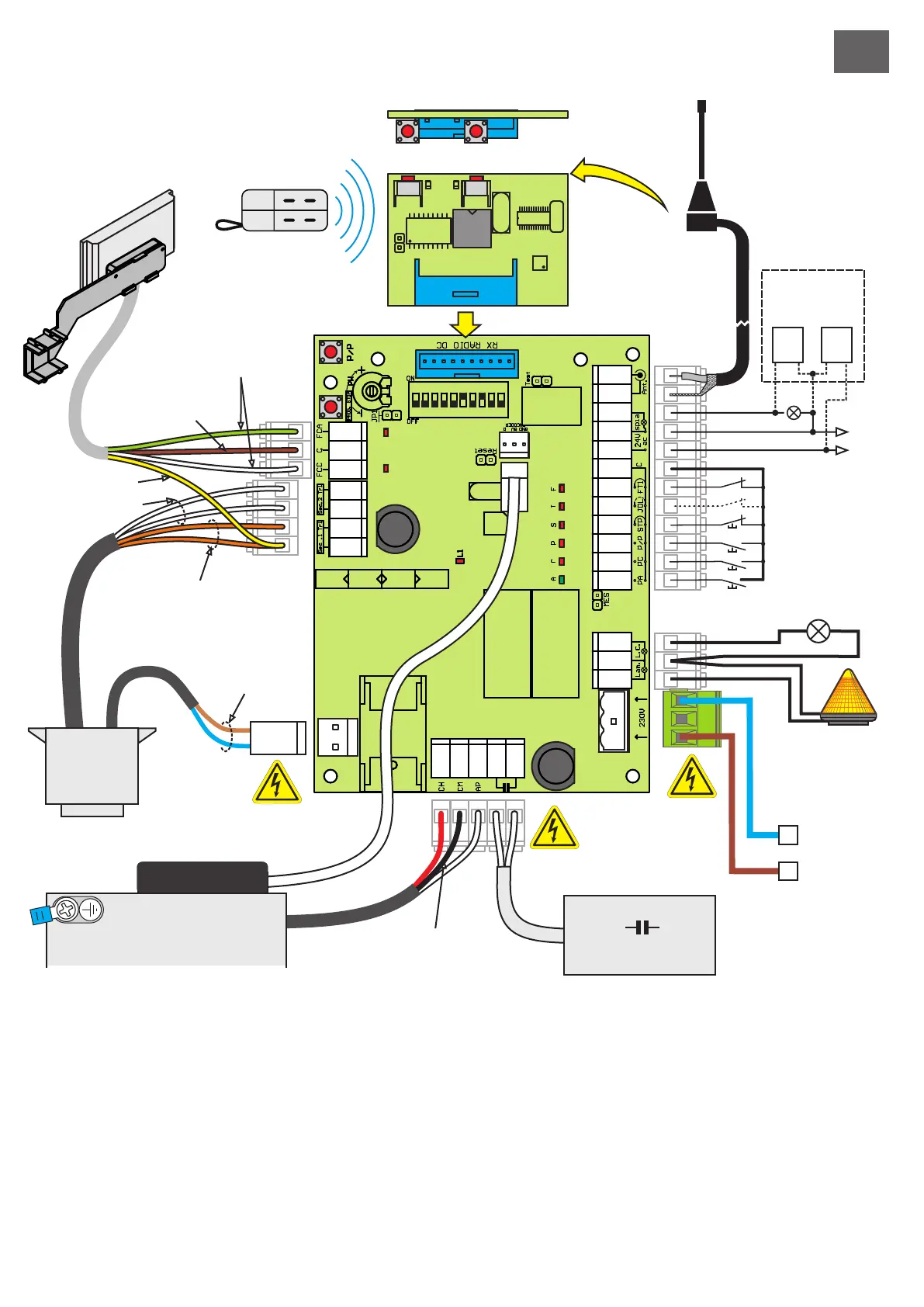
ELECTRIC CONNECTIONS
Make sure that the mains power supply has been disconnected and make the electrical connections.
Take care when stripping cables not to reduce the insulation between terminals or other metal parts.
After making the connections, check the tightness of screw terminals once more.
THE INSERTION OF AN external, Independent DISCONNECTING SWITCH (not supplied) of suitable capacity for the load Is
envisaged for the control unit power supply.
Flasher output
Courtesy light
OPENING command input
CLOSING command input
Photocell contact input
Input with selectable function
Stop command input
Step/step command input
Power supply
3
4
6
12 (com)
7
12 (com)
11
12 (com)
10
12 (com)
9
12 (com)
8
12 (com)
1 (L)
2 (N)
Function / DeviceTerm. n.
/
/
/
/
/
/
/
/
/
/
230/0,5A
230/0,5A
NO
NO
NC
NO/NC
NC
NO
230/6A
V/I max
Switches on with motor in motion.
On form start of manoeuvre until 3 minutes after
complete shutdown.
Starts gate opening.
Starts gate closing.
Reverses direction during closure.
Connect this input to the common if it is not used.
See settings of dip-switches 3 and 4.
Blocks all functions.
Connect this input to the common if it is not used.
See settings of dip-switches 1 and 2.
Connect to 230 V line.
Notes
33 34
Tips for correct Installation:
1) The cross section of the cables should be calculated according to their length and absorbed current.
2) Do not use a single cable of the "multi-core" type for all the connections (line, controls, etc.) or in common with other equipment.
3) Use at least two cables for the installation, e.g.:
cable (A) minimum wire section 1.5 sq.mm
- power supply line - courtesy / flashing light line
cable (B) minimum wire section 0.75 sq.mm
- auxiliaries power supply - controls - safety contacts.
4) When the control cables are very long (over 50 metres), de-coupling is advisable with relays mounted near the control unit.
5) Any N.C. Inputs (photocells, limit switches, fixed safety edge and stops) that are not used In the control unit should be short-
circuited with the common terminal terminal.
6) All the N.C. contacts linked with the same input should be connected in series.
7) All the N.O. contacts linked with the same input should be connected in parallel.
F6,3A
230V
1
2
3
4
5
6
7
8
9
10
1
2
3
4
5
6
7
8
9
10
11
12
13
14
15
16
17
18
19
20
21
22
23
24
27
28
29
30
31
F0,3A
24V
RECEIVER mod. OC2
P1
(P/P)
P2
(PED)
MEMORIA
TRANSMITTER
RxTx
Sec. 24Vac (Orange)
230V Flasher
230V Courtesy light
OPENING input
PROG.
STOP
P/P
CLOSING input
Step/step input
Stop input
JOLLY input
FT1 Photocell input
Common input
SPIA 24Vac CA
power supply
photocells with
FOTO-TEST
RECEIVER
ANTENNA
Com. Motor (Black)
230V primary
transformer
Sec. 12Vac (White)
24V (Yellow)
Com. (Brown)
FC(1) Green
FC(2) White
24Vac
FCC
Ap
Ch
P/P
Stop
Jolly
FT1
FCA
Power
Supply
230V 50Hz
N
L
ENCODER
Condensatore
motor