8555-M512-O1 Rev D 01/15 5
INTERCONNECTIONS
All input, output, power and option connections to the MV1 are made on the its rear panel.
Connections for the Load Cell input and the Serial I/0 are made using 9-pin "D" shaped
connectors. The Height Rod option (Detecto DHR, Digital Height Rod) and Ethernet (MVIP)
options use snap-in modular connectors. The USB port is a device (or upstream) port using an
industry standard “B” connector. The optional 12VDC wall plug-in UL/CSA listed AC power
adapter is connected using a power jack. Refer to Figure No. 1.
Optional AC Power Adapter
To power the MV1 using the optional 12VDC wall plug-in AC power adapter, connect the
plug from the adapter into the power jack on the back of the MV1 and then plug the power
adapter into the proper electrical outlet. Refer to Figure No. 1. On models requiring 220
VAC, it is the customer’s responsibility to obtain the correct power adapter plug.
Height Rod – Detecto DHR (Digital Height Rod) Option
The optional Detecto DHR (Digital Height Rod) connects to the MV1 by a snap-in modular
connector socket. Insert the modular connector of the DHR cable into the socket on the
rear of the MV1 it locks in place (a clicking sound will be heard when it is locked in place).
Load Cell
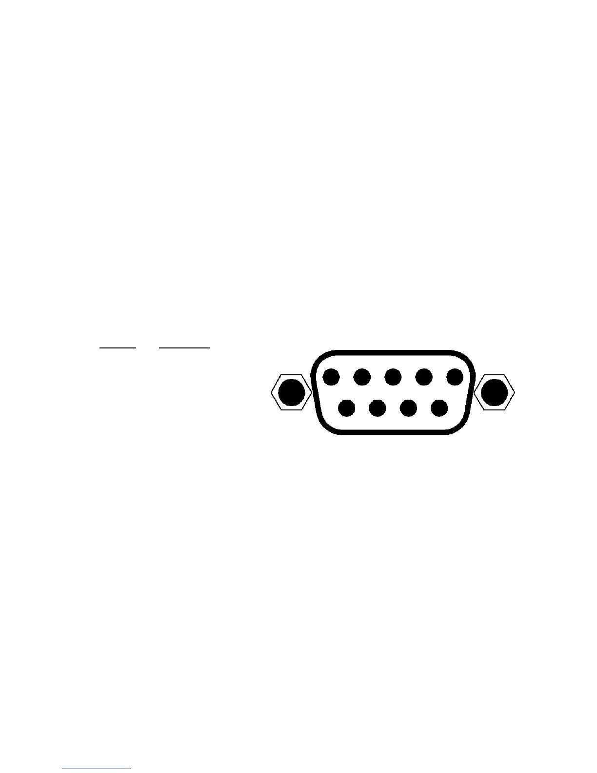
The load cell cable connects to the MV1 via a 9-pin "D" connector on the rear panel of the
MV1. Figure No. 4 shows the pin identification for the load cell connector. Make certain
that the pins are correctly identified before soldering a wire to them. Use the connector
retaining screws to hold the load cell cable connector securely to the rear panel.
PIN NO. FUNCTION
1 +EXCITATION
2 -SIGNAL
5 SHIELD
6 -EXCITATION
7 +SIGNAL
Note that pins 3, 4, 8 and 9 are
not used.
Figure No. 4
MATING CONNECTOR INFORMATION
DESCRIPTION ITEM Cardinal Part #
CONNECTOR DE9-P 6610-2379
CONNECTOR SHELL C883010001 6610-1131
USB
The USB port on the MV1 is a device (or upstream) port and uses readily available cables
with the industry standard “B” connector.
USB, Serial, Ethernet and WiFi Interface Specifications
The USB, Serial and optional Ethernet and WiFi interfaces on the MV1 can be configured
during the setup and calibration procedure or during the setup review operation. Using
either method, it is possible to select the operation of the interfaces.
The interfaces may be connected to a computer for transmission of weight and associated
data to a PC-based EMR (electronic medical record) software program. The data can be
transmitted on demand (pressing the PRINT/ENTER key) or on receipt of a command from
the computer.
5 4 3 2 1
9 8 7 6
 Loading...