ECLIPSE Service Manual Carefree of Colorado
D02 (CONT)
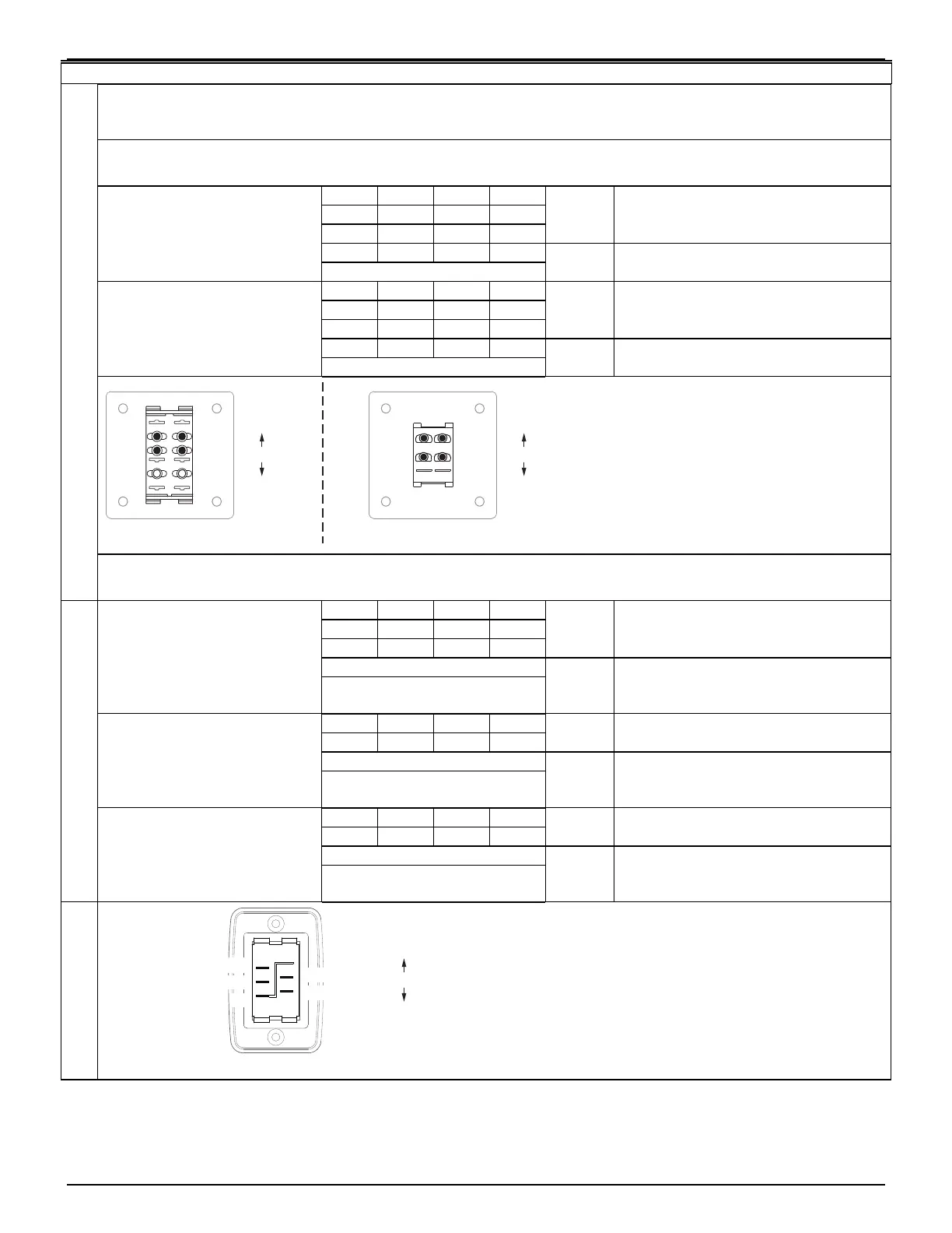
Test Switch Function – Single Switch Installation (this test requires a continuity tester)
The Patio Switch used in the Single Switch Installation is a center on that is internally cross-wired to short in the
center position to provide dynamic braking for the motor to prevent "drift" when the awning is stopped.
Test 1 is for Series I & II switches. Use Test 2 for Series III switches.
Observe continuity for switch in center position, extend position and retract position.
Pin: Center Extend Retract
3 N Y N
6 Y N Y
YES Test OK, all checks pass – go to step
1b
5B Y N N
1a Place one lead of tester
on pin 2B. Touch 2nd
lead to the other pins
one at a time.
N = no continuity, Y = continuity
NO Test failed; switch defective - replace
Pin: Center Extend Retract
3 N N Y
6 Y Y N
YES Test OK, all checks pass – Revaluate
problem, cause is not electrical
1b Place one lead of tester
on pin 5B. Touch 2nd
lead to the other pins
one at a time.
N = no continuity, Y = continuity
NO Test failed; switch defective - replace
Travelr019
Note:
The Series II switch terminals are not labeled.
The illustrations are labeled for identification purposes
in the procedures above.
Series I Switch
(Retract)
(Extend)
(Center)
6
5B
4
3
2B
1
Series II Switch
(Retract)
(Extend)
(Center)
(6)
(5B)
(3)
(2B)
E
Test 2 is for Series III switches. Use Test 1 for Series I & II switches.
Observe continuity for switch in center position, extend position and retract position.
Pin: Center Extend Retract
2 N N Y
4 N Y N
YES Test OK, all checks pass – go to step 2b
N = no continuity, Y = continuity
2a Place one lead of tester
on 12V pin (3). Touch
2nd lead to the other
pins one at a time.
All other pins should be NO in all
switch positions
NO Test failed; switch defective - replace
Pin: Center Extend Retract
2 Y Y N
YES Test OK, all checks pass – go to step 2c
N = no continuity, Y = continuity
2b Place one lead of tester
on Ground
1
pin (1).
Touch 2nd lead to the
other pins one at a time.
All other pins should be NO in all
switch positions
NO Test failed; switch defective - replace
Pin: Center Extend Retract
4 Y N Y
YES Test OK, all checks pass – Revaluate
problem, cause is not electrical
N = no continuity, Y = continuity
2c Place one lead of tester
on Ground
2
pin (5).
Touch 2nd lead to the
other pins one at a time.
All other pins should be NO in all
switch positions
NO Test failed; switch defective - replace
Travelr019a
Note:
The Series III switch terminals are not labeled.
The illustration is labeled for identification purposes
in the procedures above.
(Retract)
(Extend)
(Center)
Ground
1
(1)
12V (3)
Retract (2)
(5) Ground
2
(4) Extend
Series III Switch
16 052547-301r7