Carefree of Colorado Service Manual ECLIPSE
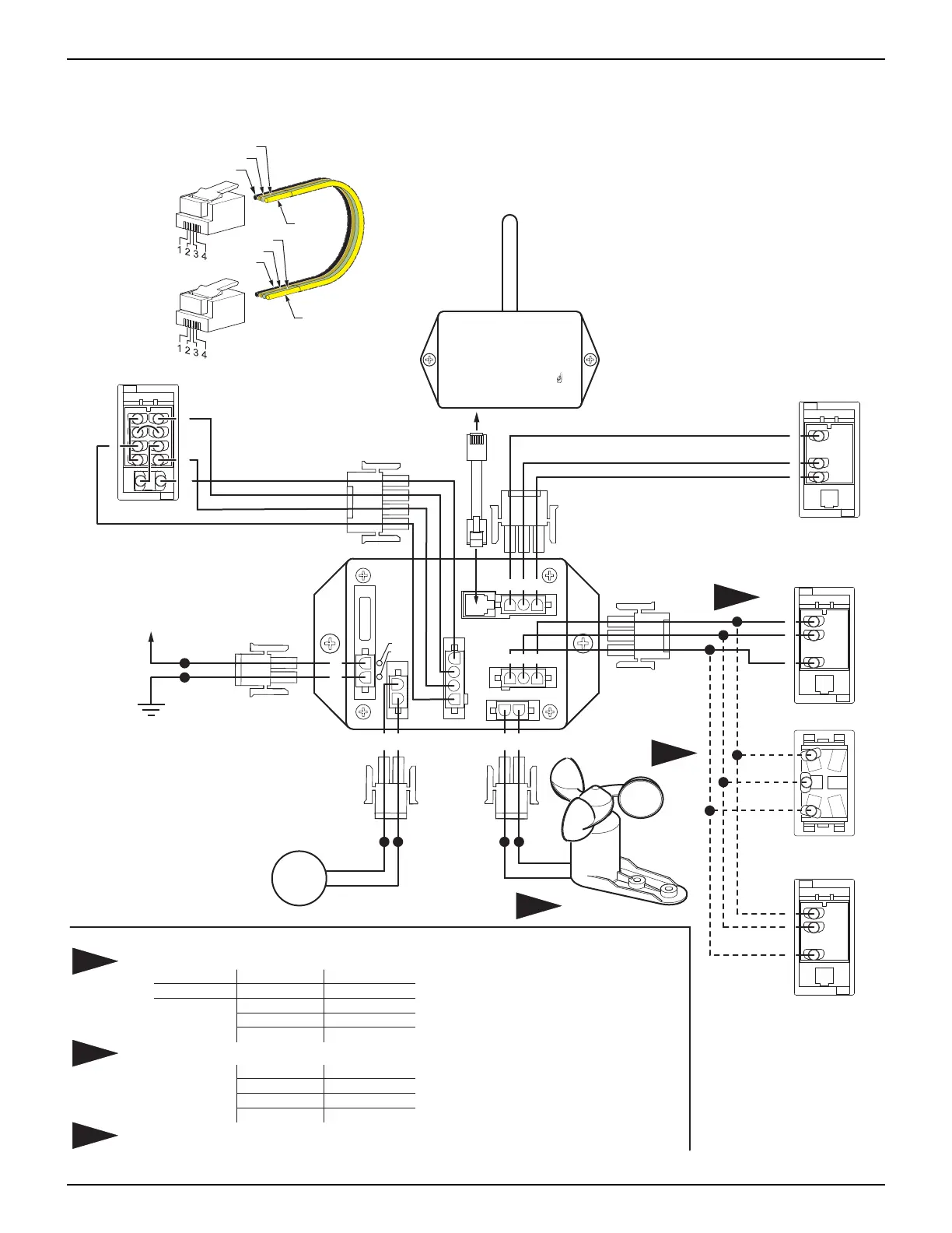
WIRING DIAGRAM - WINDSMART
The system has been discontinued in 2007 and not available for original or upgrade installations.
Superseded by the 12V Direct Response System.
052547-301r7 25
TO
EYE PORT
on RP24
Program
Mode
Press to Learn
Transmitter
UP
ANEMOMETER
PATIO SWITCH
WIND SPEED
SWITCH
RR24
(Optional)
MODE SWITCH
A B
MOTOR
FUSE (15 A)
+12V
GROUND
15
1
7
5
3
2
8
6
4
9
10
Mode Switch
Wind Speed
Switch
910
1
7
5
14 15 16
1
7
3
11 12 13
Patio Switch
RF Receiver
1
7
3
Additional
Patio Switch
+12VDC
Ground
Anemometer
5
6
7
8
1
2
BA
M
Awning Motor
HI
LOW
WINDSMART ON
COM
EXT
RET
COM
EXT
RET
COM
+12VDC
POWER ON
GROUND
WS006a
BLACK
RED
BLUE
GRAY
BRN
YELLOW
Eclipse
Exterior Switch
GRAY
BROWN
YELLOW
Control
Box
OR
RED
BLK
GRN
Wire colors for anemometer are not pin specific.
Early versions of the Eclipse Exterior Switch cable may have different wire colors.
Jacket Color:
Wire Colors:
Previous Color
Gray
Black1
Black2
Yellow/Green
Current Color
Black or White
Brown
Gray
Yellow
Early versions of the Patio Switch harness may have different wire colors.
Previous Color
Black
Red
Blue
Current Color
Brown
Gray
Yellow
1
NOTES:
2
3
3
1
2
Black
Red
Green
Black
Yellow
Red
Green
Yellow
Cables are 4-wire RJ11
terminated phone cord
(straight, no twist).
Phone Cable
RED
BLACK