Carefree of Colorado Service Manual ECLIPSE
COMMON TEST PROCEDURES
These common tests are referred to in the diagnostics procedures.
CT01 T
ESTING A SWITCH AND HARNESS
Disconnect the switch harness connectors from the control box and remove the plate and switches from the mounting
surface.
YES
Switch mounted OK; go to test B
A
(Series I) Confirm switch is mounted in correct position and
correctly oriented. The lens or lens caps should be on the
bottom of the switch as indicated by the shaded area
NO
Carefully remove the switch, rotate
180˚ and reinstall in panel.
Reconnect harnesses and retest
YES
Switch wired OK; go to test C
B
Confirm switch is wired correctly. Use the wiring diagram and
confirm the wires from the switch to the connector are
correctly placed.
NO
Rewire the switch according to the
wiring diagram
Test the Switch function (this test requires a continuity tester
Do not remove the wires from the back of the switch. From the numbered terminal of the switch, trace the wire to the
connector; place the tester leads on the connector pins. The pins are not marked on the connector.
Steps 1 through 5 are for the Extend/Retract and Wind Speed Switches. Refer to step 6 for the Series I Mode
Switch.
YES
Circuit(s) are open, go to step 2 1. Using a continuity tester, place one lead on common pin
(3 for Extend/Retract, 5 for Windspeed). Place the second
lead on pin 1. Put the switch in the center position and
measure the continuity. Move the second lead to pin 7,
measure the continuity. Circit should be open
NO
Circuit(s) are closed (continuity exists);
switch assy is defective-replace
YES
Circuit closed; go to step 3 2. Place the second lead on pin 1. Press the switch down
("Extend" for Extend/Retract, "Lo" for sensitivity). Is circuit
closed?
NO
Circuit open, switch defective - replace
YES
Circuit open: go to step 4 3. Leave the leads in position of step 2. Press the switch up
("Retract" for Extend/Retract, "Hi" for sensitivity). Is the
circuit open?
NO
Circuit closed, switch defective - replace
YES
Circuit open: go to step 5 4. Move the second lead to pin 7. Press the switch down
("Extend" for Extend/Retract, "Lo" for sensitivity). Is the
circuit open?
NO
Circuit closed, switch defective - replace
YES
Circuit closed; go to step 6 5. Leave the leads in position of step 4. Press the switch up
("Retract" for Extend/Retract, "Hi" for sensitivity). Is the
circuit closed?
NO
Circuit open, switch defective - replace
YES
Switch tests OK, return to diagnostic 6. For Series I Mode Switch only - Follow steps 1 through 5
using pins 5, 2 and 8 respectively
NO
Test Failed; switch defective
YES
Switch tests OK, return to diagnostic
C
7. For Series III On/Off Switch only - Place on lead on each
terminal. With switch in OFF is the circuit open? With the
switch in ON, is the circuit closed?
NO
Test Failed; switch defective
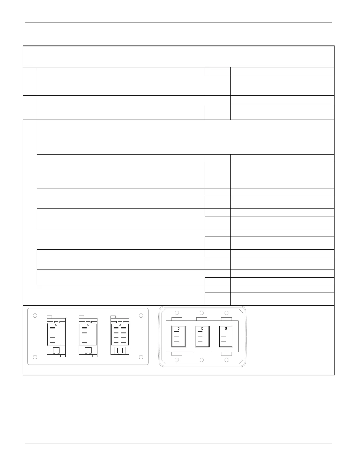
DR042
Series III
Note:
The Series III switch terminals
are not labeled. The illustrations are
labeled for identification purposes
in the procedures above.
1
7
5
3
2
8
6
4
9
10
Mode
1
7
3
PatioWind Speed
1
7
5
Series I
On/OffMotion Extend/
Retract
(1)
(7)
(5)
(1)
(7)
(3)
052547-301r7 21