Carefree of Colorado Service Manual ECLIPSE
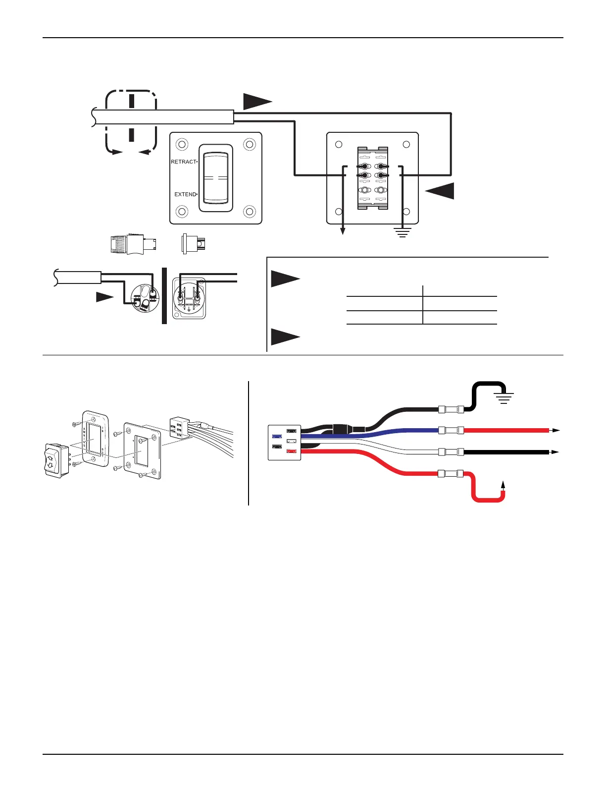
WIRING DIAGRAM - SINGLE SWITCH PRIOR TO JULY 2010
This switch hardware has been discontinued. For wiring replacement switches, use instructions provided
with the Single Switch Kit.
E0008
Black Red
Carefree of Colorado
L
N
A
L
N
Black
Black
Red
Red
6
5B
4
3
2B
1
1
1
Wire color from the motor may deviate on some models.
NOTE:
Standard Color
Red
Black
Deviation Color
Yellow
Brown
Detail A
Optional Wall Mount Connector
Vehicle
Ground
+12VDC
Motor
Motor
Front View of
Switch Panel
Rear View of
Switch Panel
1
2
Terminals 1 and 4 are capped with insulated connectors.
These terminals must remain capped at all times.
Rear View of Connectors Shown
2
WIRING DIAGRAM - SINGLE SWITCH - JULY 2010 AND ON
SK005a
RETRACT
EXTEND
Carefree of Colorado
To Ground
To +12VDC
BLACK Motor Wire
RED Motor Wire
RED
BLACK
WHITE
BLUE
NOTES:
1. If connector block is oriented with wires to the left, reverse the motor wires. W
HITE connector block wire
goes to
RED motor wire, BLUE connector wire goes to BLACK motor wire.
2. For first time replacement installation, refer to installation instructions furnished with replacement switch
kit.
052547-301r7 23