ECLIPSE Service Manual Carefree of Colorado
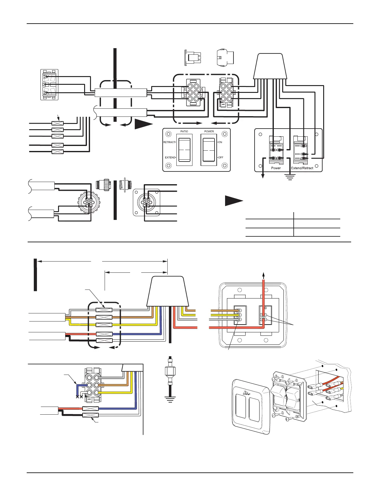
WIRING DIAGRAM - MULTIPLE SWITCH PRIOR TO JULY 2010
This switch hardware has been discontinued. For wiring replacement switches, use the schematic below.
Red
Black
Blue
White
Gray
Brown
Yellow
Gray
Brown
Yellow
Rear View of Connectors Shown
Wall
3
1
7
Gray
Yellow
Brown
1
5
2
6
Red
Black
Vehicle
Ground
+12VDC
Exterior Switch
Motor
Red
Black
Blue
White
Gray
Brown
Yellow
Gray
Brown
Yellow
Detail
A
lternate Wire Connection
Front View of
Switch Panel
Rear View of
Switch Panel
E0032a
Carefree of Colorado
6
4
5
1
2
1
2
6
4
5
B
12
35
67
Red
Black
Motor
21
53
76
Gray
Yellow
Brown
Exterior
Switch
Red
Black
Gray
Yellow
Brown
Detail
B
Optional Wall Mount Connector
A
Relay
Module
1
Wire color from the motor may deviate
on early models.
NOTE:
Standard Color
Red
Black
Deviation Color
Yellow
Brown
1
Butt Splice (5 plcs)
Rear View of Connectors Shown
Exterior Switch
Gray
Brown
Yellow
WIRING DIAGRAM - MULTIPLE SWITCH AFTER JULY 2010
RETRACT
ON
EXTEND
Awning Control
OFF
E0064
To +12VDC
On/OffExtend/Retract
Rear View of
Switch Assy
Gray
Brown
Yellow
Chassis
Ground
Exterior Switch
Motor
Red
Black
Blue
White
Gray
Brown
Yellow
A
Butt Splice
(5 plcs)
Relay
Module
Gray
Yellow
Brown
Red
Detail
A
(When Exterior Switch Not Used)
1
2
6
4
5
Butt Splice (2 plcs)
Trim Only Blue
and White Wires
from Connector
Motor
Red
Black
Blue
White
Gray
Brown
Yellow
F
M
Black
.187, 14-16awg
Female Spade
Terminals
(qty: 2)
.25, 14-16awg
Spade Terminals
1 Male, 1 Female
.187, 18-20awg
Female Spade Terminals
(qty: 3)
Vehicle Wall
48"
(Max. Distance with Furnished Wires)
16”
(ref)
24 052547-301r7