ECLIPSE Service Manual Carefree of Colorado
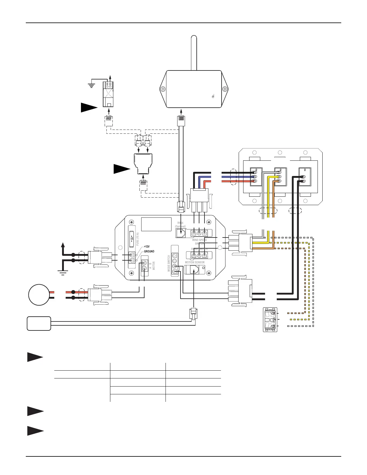
WIRING DIAGRAM - DIRECT RESPONSE AFTER JULY 2010
28 052547-301r7
Carefree of Colorado
12V DIRECT RESPONSE
CONTROL BOX
PART NO. 060574-003
14 15 16
11
12
13
TO
EYE PORT
on RP24
Program
Mode
Press to Learn
Transmitter
UP
RF Reciever
+12VDC
Ground
Motion
Sensor
5
6
7
8
1
2
BA
M
DR005c
Control
Box
Ignition Switched
+12VDC
12VDC
Ground
Splitter
2
1
Ignition
Lockout
Sensor
(Optional)
On/Off
Black
Red
Blue
Gray
Brown
Yellow
Black
Black
Red
Black
Additional Extend/Retract Switch
Brown
Gray
Yellow
Ext
Ret
Com
Motion
Extend/
Retract
N
OTES:
1
Early versions of the Eclipse Exterior Switch cable may have different wire colors.
Current Color Previous Color
Jacket Color: Black or White Gray
Brown Black1
Wire Colors: Gray Black2
Yellow Yellow/Green
2
Splitter is used only when the optional Lock-Out Sensor is installed. Connect the RF receiver
directly to the control box if Lock-Out is not installed.
3
The optional Lock-Out Sensor can only be used with control boxes marked "060574-003".
Wires for the sensor are not pin specific.