FCM electronic regulator Cod. +302235300 - Rel. 2.0 del 30/11/98
3
3 Buttons and displayed indications
3.1 Front panel
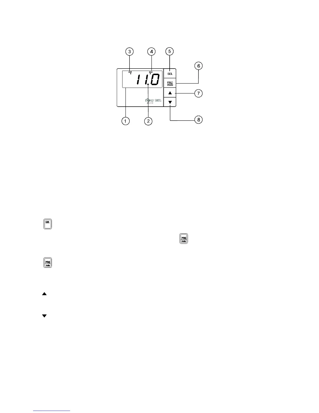
Fig. 1
1 - Display:
• it displays the value of the connected probes or the status of the control, as programmed (parameter C33);
• in the event of alarm, it displays the alarm code;
• during the programming it displays the parameter codes and their values.
2 - LED decimal:
• it turns on when the value being controlled is displayed with decimal point resolution.
3 - LED OUT:
• it turns on when the 0÷10 V output energises (output voltage different from 0 V);
• it flashes when the 0÷10 V output reaches its maximum programmed value.
4 - LED AUX:
• it turns on or flashes according to the selected operating mode.
5 - button:
• displays and/or sets the set-point; if pressed together with the PRG/mute button for 5 seconds, it allows the password to be
inserted and the configuration parameters to be accessed (parameters with code “Cxx” ).
6 - button:
• if pressed for 5 seconds, it allows the more frequently used parameters to be accessed (parameters with code “Pxx”);
• in the event of alarm it silences the buzzer; if pressed again, resets the alarm signal, as long as the cause of the alarm has been
removed.
7 -
button:
• while being pressed it displays the value of probe 1;
• during the programming it moves to the next parameter or increases the value of the parameter.
8 - button:
• while being pressed it displays the value of probe 2;
• during the programming it moves back to the previous parameter or decreases the value of the parameter.