FCM electronic regulator - Preliminary version Cod. +302235300 - Rel. 2.0 del 30/11/98
33
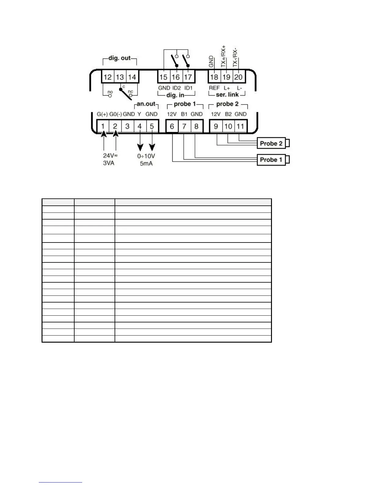
12 Wiring diagram
12.1 Terminal block
Terminal Symbol Description
1 G(+) Power supply (positive pole when dc voltage)
2 G0(-) Power supply (negative pole when dc voltage)
3 GND Cable shielding
4 Y
0÷10Vdc analogue output
5 GND
GND for 0÷10Vdc analogue output
6 +12V Auxiliary power supply
7 B1 Input probe 1
8 GND GND for input probe 1
9 +12V Auxiliary power supply
10 B2 Input probe 2
11 GND GND for input probe 2
12 NO Relay output: normally open contact
13 C Relay output: common
14 NC Relay output: normally closed contact
15 GND Common for digital inputs
16 ID2 Digital input 2
17 ID1 Digital input 1
18 REF Serial line RS-485: reference
19 TX+/RX+ Serial line RS-485: positive pole
20 TX-/RX- Serial line RS-485: negative pole
Terminals G0(-) and GND are internally connected between them.
Terminal REF is internally connected to G0 and GND by a 22Ω resistance.
12.2 Power supply:
• • alternate voltage: half-wave rectification stage (should you use a dedicated transformer to power the regulator, keep into
consideration an increase - at least three times over - in heating due to the unbalance load of the rectifier).
• continuous voltage: polarity inversion will not damage the instrument but rather prevent it from functioning.
 Loading...


