10 Technical specifications
10.1 MTSB*
43
MasterCella Split - cod. +030221396 rel. 1.2 - 03.12.2004
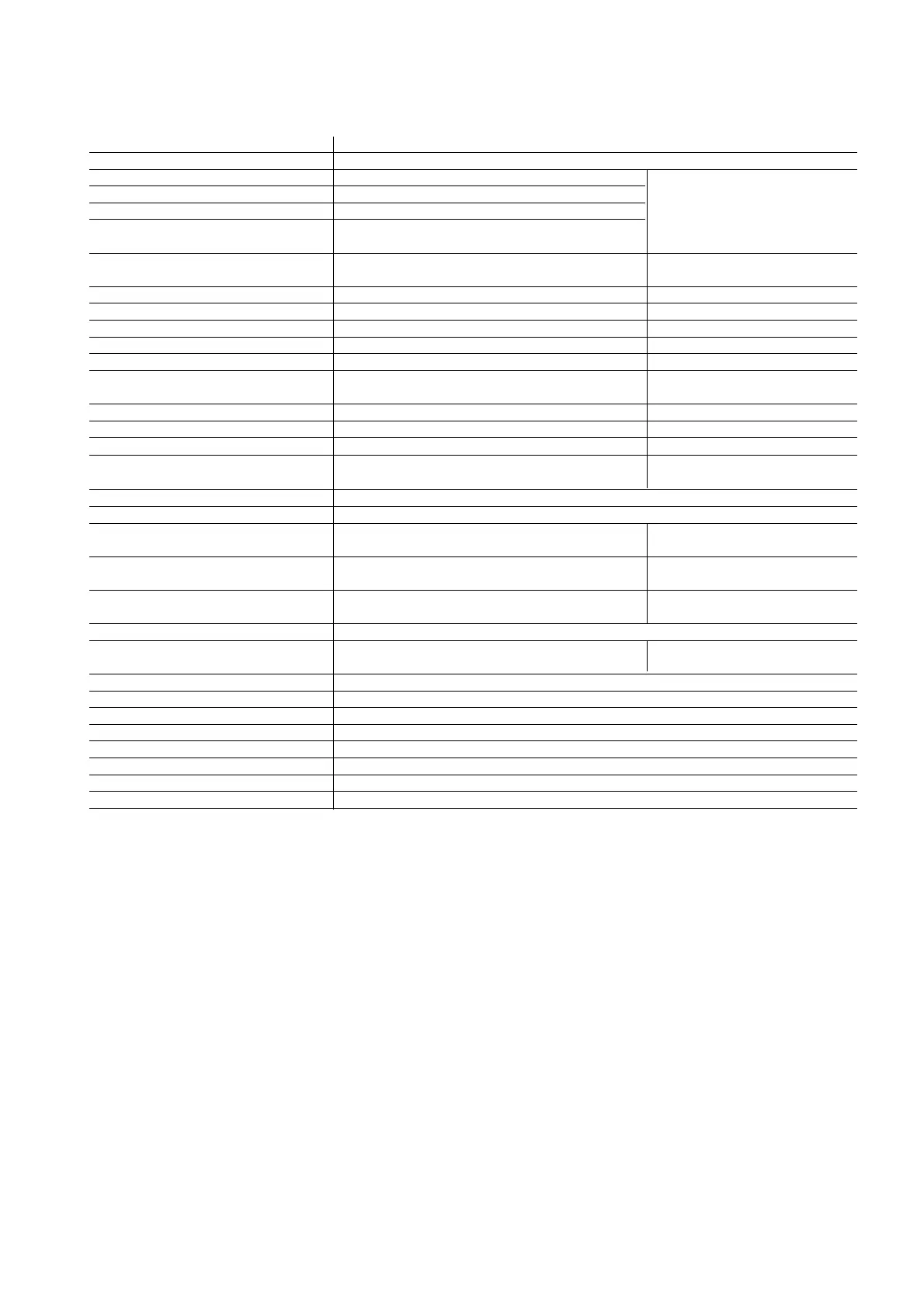
power supply 230 Vac +10/-15 % 50/60 Hz
power consumption 5 VA asbsorbed at 230 Vac
probe inputs 3 NTC probe cable max. length for all
inputs - accuracy NTC Std CAREL 10 K 25 ˚C - +/- 1 ˚C the inputs= 30 m
range of measurement -50T90 °C (-58T195°F) resolution 0,1°C
digital inputs 2 free contact not opto-insulated
open-closed contact 10 Vdc - 10 mA Typ.
Relay outputs: action and type and No. of type 1B action (microdisconn.) EN60730 100.000op. UL250 Vac 30.000op. disconnection
manoeuvre cycles Note: changeover relay only for NO or NC
2HP compressor contact NO 10(10) A-250 Vac 12 A 10FLA 60LRA
(COMPR) Motor load 2HP max. 10A max 100000 op UL250 Vac
defrost 16A (DEFR) SPDT contact 14(2) A-250 Vac (NO) , 2(2A) NC 14 A Res. (NO), 2 A(NC)
fan10A (FAN) contact NO 4(2) A-250 Vac 4 A 2FLA 12LRA
alarm10A (ALARM) SPDT contact 4(2) A-250 Vac 4A 2FLA 12LRA
aux. 1 - Light 16A (AUX 1) contact NO 10(10) A-250 Vac
fluorescent Lamp 1000 VA-110 uF max. 15000 op. 12 A 10FLA 60LRA
aux. 2 - Antifog.10A(AUX2) contact NO 4(2) A-250 Vac 4 A 2FLA 12LRA
connections: max. continuous current for all the activated relays 25A
power supply terminals screw terminals 30 A max. 250 Vac max. section cables= 4mm
2
for load power supply and control
faston load power supply and earth faston 6.3 mm for cables with recommended section bearing connections for load power
connection 2.5 mm
2
(minimum 1.5 mm
2
) max. current 15 A supply L, N, EARTH
terminals for I/O signals screw terminals for cables with section from 0.5 to 1.5mm
2
mounting wall mounting (back-of-board) using plastic or metal spacers
terminal serial connection 485, 3-wire, max. length 100 m: power supply from transformer
• MTST terminal 220/24 Vac-4 VA
serial connection TTL with 4 wires of max. length 10 m: power supply supplied by the
• optional terminal PST Large control 12 Vdc 120 mA
classification according to protection against Class II for appropriate installations double insulation transformer and relay
electric shock distances for reinforced insulation
RTC Clock management days :hours :min. :s weekly day (0-7) accuracy +/-20 ppm (+/-10 min/year)
RTC data holding with rechargeable battery lithium 7mAh complete recharge in about 20 hours
(at about 6 months at full charge)
operating conditions -10T50 °C humidity not condensing
storage conditions -20T70 °C humidity not condensing
ambient (pollution type) normal
PTI of insulating materials 250 V
period of electric. stress of the insulating parts long
categ. of resist. to heat and fire D (UL94 - V0)
immununity against voltage surges Category 1
software class and structure class A
(*) T OFF minimum between two following motor load starting is 60s or more.
Warning: for the characteristics of the displays MTST and PST large refer to their technical leaflets respectively. In the applications, the probes and
the digital inputs placed on the display MTST can be used. This is not a feature of the PST display.
SAFETY STANDARD: in compliance with the European laws.
Installation precautions:
• connection cables should be suitable for 90 °C operation;
• for the card mounting use only plastic spacers and consider at least 10 mm distance from the conductive parts near to the card connections;
• the probe connections and the digital inputs must be lower than 30 m of distance, use the proper separation measurements of the cables for com
plying with the immunity laws;
• block properly the connection cables of the outputs to avoid any contact with very low voltage parts.