EasyManuals Logo

Carel pCO1 User Manual

Carel pCO1
56 pages
To Next Page IconTo Next Page
To Previous Page IconTo Previous Page
Page #45 background imageLoading...
Page #45 background image
La figura seguente (Fig. 8.2) indica una configurazione nella quale
viene ulteriormente facilitato il cablaggio dei carichi. Bisogna comunque
tenere in considerazione che il max valore di corrente sopportabile
da ciascun morsetto è 8 A.
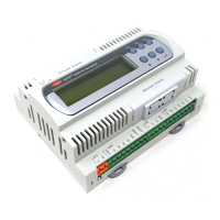
The following figure (Fig. 8.2) shows a configuration in which the wiring
of the loads is further simplified. In any case, always remember that
the max current at each terminal must be 8A.
45
pCO
1
manual - cod. +030221840 rel. 1.0 - 09/07/02
C1
NO1
NO2
NO3
C1
C4
NO4
NO5
NO6
C4
C7
NO7
C7
NO8
C8
NC8
NO12
C12
NC12
NO13
C13
NC13
C9
NO9
NO10
NO11
C9
Fuse
Programming Key
J10
J11
J12
J13
J14
J15
J16
J17
J18
J9
L
N
digital output 1
digital output 2
digital output 3
digital output 4
digital output 5
digital output 6
digital output 7
digital output 8
digital output 9
digital output 10
digital output 11
digital output 12
digital output 13
CLOCK CARD
ANALOG SELECTION
CLOCK CARD
SERIAL CARD
Fig. 8.2

Other manuals for Carel pCO1

Questions and Answers:

Question and Answer IconNeed help?

Do you have a question about the Carel pCO1 and is the answer not in the manual?

Carel pCO1 Specifications

General IconGeneral
BrandCarel
ModelpCO1
CategoryChiller
LanguageEnglish

Related product manuals