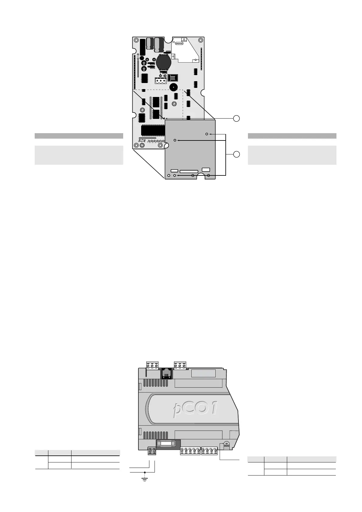
3.9.3 Scheda schermo (opzione per stampante)
Per tutti i modelli del terminale grafico pCO
esiste la possibilità di inserire una scheda
opzionale per la gestione di una stampante
seriale, nel connettore a pettine
contrassegnato dal numero 2 indicato in
Fig. 3.9.3.1.
Per fare ciò occorre prima asportare la
scheda di protezione localizzata nell’area
riservata alla scheda stampante opzionale.
La funzione è quella di aumentare
l’immunità ai disturbi del terminale; il relativo
fissaggio si effettua mediante tre viti da
avvitare nei tre fori individuati dal numero 1
nella Fig. 3.9.3.1.
n. descrizione
1fori di fissaggio
2tacca di riferimento del pin 1 della
EPROM e relativa serigrafia a bordo
scheda
Tab. 3.9.3.1
4. INSTALLAZIONE
4.1 Ancoraggio del pCO
1
Il pCO
1
va installato su guida DIN e per il fissaggio, è sufficiente una
leggera pressione del dispositivo, preventivamente appoggiato in
corrispondenza della guida stessa. Lo scatto delle linguette posteriori
ne determina il bloccaggio alla guida.
Lo smontaggio, invece, avviene altrettanto semplicemente, curando di
fare leva con un cacciavite, sul foro di sgancio delle linguette
medesime per sollevarle.
Le linguette sono tenute in posizione di blocco da molle di richiamo.
4.2 Alimentazione
Il pCO
1
può essere alimentato a: 22/38 Vdc e 24 Vac ±15%, 50/60 Hz
con una potenza massima assorbita Pmax= 13 W.
Per l’alimentazione in corrente alternata si deve utilizzare un trasformatore
di sicurezza in Classe II, di almeno 40 VA e con 24 Vac in uscita. Se si
prevede di alimentare più controllori pCO
1
con il medesimo trasformatore,
la potenza nominale di quest’ultimo deve essere pari a n x 40 VA, dove “n”
è il numero di controllori indipendentemente dalla versione del controllore.
Si raccomanda di separare l’alimentazione del/i controllore/i pCO
1
e
terminale dall’alimentazione del resto dei
dispositivi elettrici (contattori di potenza ed
altri componenti elettromeccanici),
all’interno del quadro elettrico.
Qualora il secondario del trasformatore sia
posto a terra, verificare che il conduttore di
terra deve essere collegato al morsetto G0.
Se si alimentano più schede pCO
1
collegate
in rete pLAN, assicurarsi che siano rispettati
i riferimenti G e G0 (G0 dev’essere lo stesso
per tutte le schede).
La tabella seguente riassume gli stati del
LED dell'alimentazione.
LED stato descrizione
giallo acceso alimentazione presente
spento alimentazione assente
Tab. 4.2.1
3.9.3 Protective shield (optional printer card)
For all pCO graphic terminal models an
optional card can be inserted in the pin
connector marked by number 2 in
Fig. 3.9.3.1. for managing a serial printer.
To insert the card, first remove the
protective shield in the area reserved for
the optional printer card.The function of
the shield is to increase immunity against
terminal disturbances; the card is fitted by
tightening the three screws in the three
holes marked by the number 1 in
Fig. 3.9.3.1.
no. description
1mounting holes
2reference notch for pin 1 on the
EPROM and corresponding
silk-screening on the card
Table 3.9.3.1
4. INSTALLATION
4.1 Anchoring the pCO
1
The pCO
1
should be installed on a DIN rail.To fasten the unit, press it
lightly against the rail.The rear tabs will click into place, locking the unit
to the rail.
Removing the unit is just as simple, using a screwdriver through the
release slot to lever and lift the tabs.
The tabs are kept in the locked position by springs.
4.2 Power supply
The pCO
1
can be powered at: 22/38Vdc and 24Vac ±15%, 50/60 Hz,
with a maximum power input Pmax= 13W.
For alternating current power supplies, during installation use a Class II
safety transformer, rated to at least 40VA and with a 24Vac output.To
supply more than one pCO
1
controller with the same transformer, its
rated power must be n x 40VA, where n is the number of controllers
supplied by the transformer, independently of the version of the controller.
The power supply to the pCO
1
controller/controllers and the
terminal/terminals must be separated from
the power supply to the other electrical
devices (power contactors and other
electromechanical components), inside the
electrical panel.
If the transformer secondary is earthed,
make sure that the ground wire is
connected to terminal G0. When powering a
series of pCO
1
boards connected in a pLAN
network, make sure that the G and G0
connections are correct (G0 must be same
for all the boards).
The table below summarises the possible
status of the power LED.
LED status description
yellow on power supply present
off power supply absent
Table 4.2.1
19
pCO
1
manual - cod. +030221840 rel. 1.0 - 09/07/02

 Loading...


