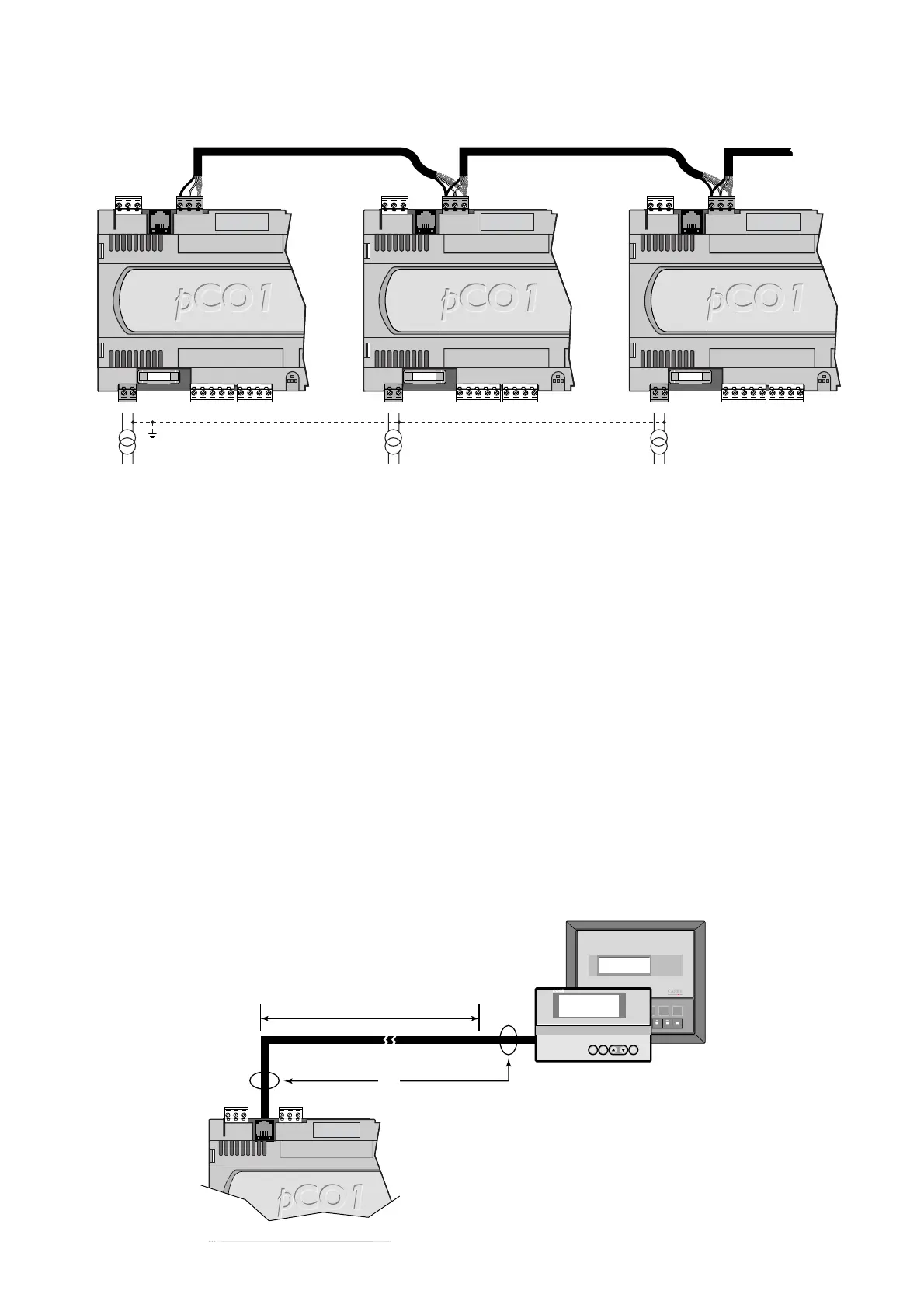
La Fig. 5.4.3 rappresenta lo schema di più schede collegate in rete
pLAN alimentate da trasformatori diversi con unico riferimento di terra;
questa è una tipica applicazione di più schede che fanno parte di
quadri elettrici diversi.
AVVERTENZE IMPORTANTI:
• il collegamento a terra deve essere effettuato sulla stessa linea di
terra (stesso polo di terra, per tutte le schede pCO
1
);
• con queste configurazioni (Figg. 5.4.1, .2 e .3) è necessario installare
trasformatori di sicurezza in Classe II.
5.5 Remotazione terminale con rete pLAN
Quando le schede pCO
1
sono connesse in rete pLAN il terminale può
essere remotato fino a 50 metri usando cavo di tipo telefonico, mentre
può essere remotato fino a 200 metri se si usa un cavo achermato,
tipo AWG. Di seguito sono rappresentati gli schemi di collegamento
delle varie configurazioni.
5.5.1 Remotazione terminale con rete pLAN con cavo telefonico
Per tale remotazione si prescrive l'inserimento di due ferriti, cod.
0907858AXX, in corrispondenza delle indicazioni relative alla lettera F
della Fig. 5.5.1.1. Le Figg. 5.5.1.2a e 5.5.1.2b raffigurano
rispettivamente la ferrite da installare, in posizione aperta e chiusa.
Le ferriti vanno montate sul cavo telefonico di collegamento, una lato
pCO
1
(vedi Fig. 5.5.1.3) e l'altra lato terminale (vedi Fig. 5.5.1.4).
Nota: Il terminale grafico, a differenza degli altri modelli LCD, richiede
una alimentazione a 24Vac da portare sugli appositi morsetti plug-In
(morsetti G e G0). Questa può essere la stessa linea che alimenta il
pCO
1
(in questo caso rispettare la corrispondenza G e G0) oppure può
essere fornita da un altro trasformatore; in questo caso non collegare il
secondario a terra.
AVVERTENZA: il
cavo telefonico deve
uscire
perpendicolarmente
dal pCO
1
.
Fig. 5.4.3 shows a diagram of a number of boards connected in a
pLAN network and powered by different transformers with the same
ground; this is a typical application for a number of boards inside
different electrical panels.
IMPORTANT WARNINGS:
•the earth connection must be made to the same ground (same
ground pole, for all the pCO
1
boards);
•with these configurations (Figs.5.4.1, 2, 3) Class II safety
transformers must be installed.
5.5 Remote installation of the terminal in a pLAN network
When pCO
1
boards are connected in a pLAN network, the terminal
can be remotely-installed at a distance of up to 50metres, if using a
telephone-type cable, while it can be located at a distance of up to
200metres if using an AWG shielded cable.The following figures show
the connection diagrams for the various configurations.
5.5.1 Remote installation of the terminal in a pLAN network using
a telephone cable
This type of remote installation requires the insertion of two ferrites,
code 0907858AXX, at the markings with the letter F in Fig. 5.5.1.1.
Figs. 5.5.1.2a and 5.5.1.2b show respectively the ferrites to be installed
the open and closed position.
The ferrites are mounted on the telephone connection cable, one on
the pCO
1
side (see Fig.
5.5.1.3) and the other on
the terminal side
(see Fig. 5.5.1.4).
Note:The graphic
terminal, unlike the other
LCD models, requires a
24Vac power supply
from the Plug-In
terminals (terminals G
and G0).This may be
the same line that
powers the pCO
1
(in this case, make sure G and G0 correspond), or
alternatively may be supplied by another transformer; in this case,
do not earthy the secondary.
WARNING: the telephone cable must exit the pCO
1
perpendicularly.
35
pCO
1
manual - cod. +030221840 rel. 1.0 - 09/07/02

 Loading...


