11. MONTAGGIO TERMINALE UTENTE
11.1 Montaggio a pannello
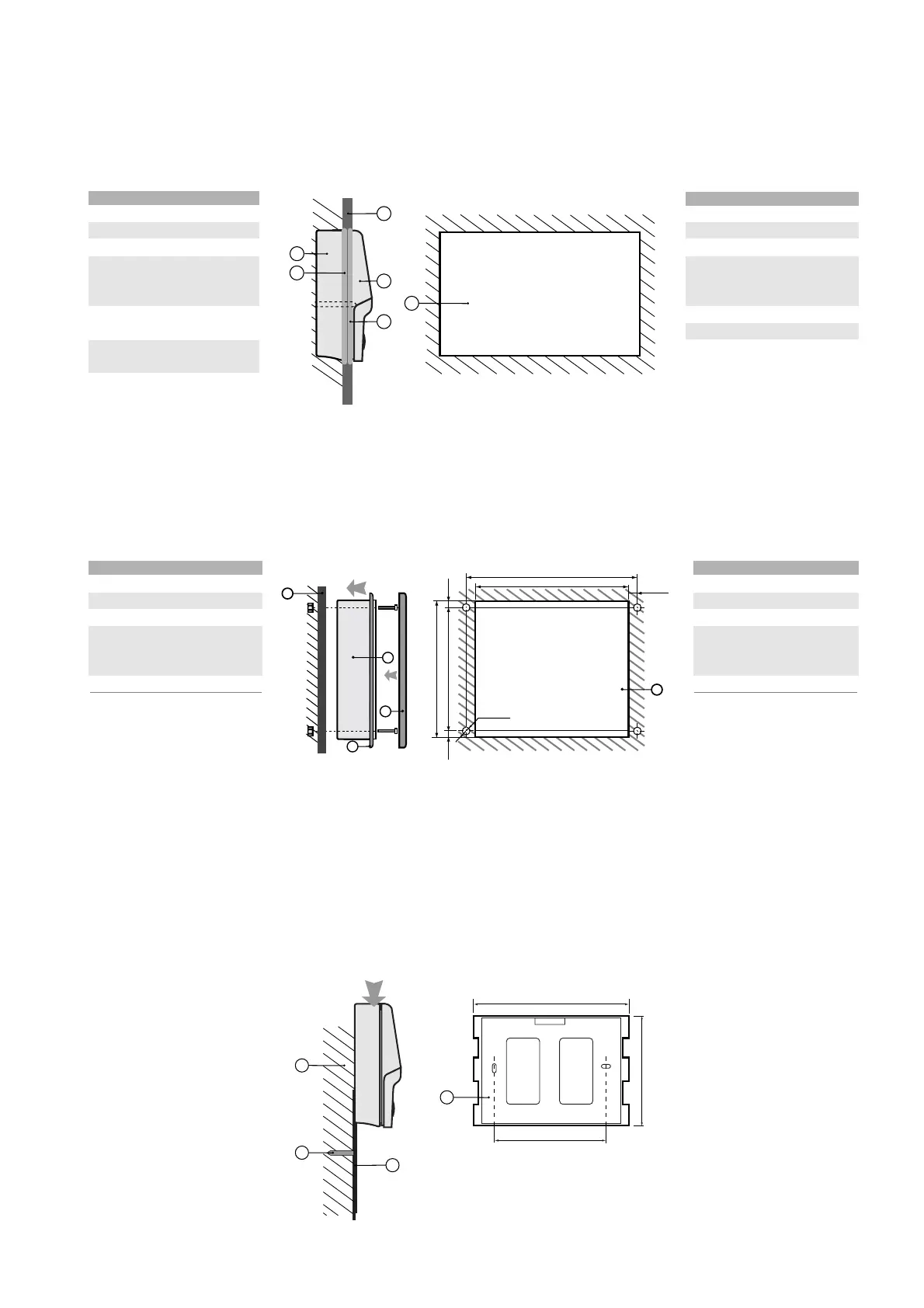
11.1.1 PCOT*
Riferimenti Fig. 11.1.1.1, (dimensioni in mm).
n. descrizione
1 coperchio posteriore
2 pannello
3 coperchio anteriore
4dime di foratura (tolleranza
finestra: -0,5 / +1 mm sulle
dimens. indicate)
5 guarnizione per il coperchio
posteriore
6 guarnizione per il coperchio
anteriore
Tab. 11.1.1.1
11.1.2 PCOI*
Riferimenti Fig. 11.1.2.1, (dimensioni in mm).
n. descrizione
1cornice esterna
2 pannello
3terminale
4dima di foratura (tolleranza
finestra: ± 0,5 mm sulle
dimensioni indicate)
5 guarnizione frontale
Tab. 9.1.2.1
AVVERTENZA: lo spessore
massimo del pannello deve
essere di 6 mm.
11.2 Montaggio a parete
Il montaggio a parete prevede l'utilizzo di un'apposita staffa di
fissaggio e di una scatola da parete standard a 3 moduli per
interruttori, al fine di consentire il passaggio dei cavi. Con riferimento
alla Fig. 9.2.1, fissare la staffa (1) alla parete (3) utilizzando la vite (2);
incastrare il dorso dello strumento alla staffa.
11. USER TERMINAL INSTALLATION
11.1 Panel installation
11.1.1 PCOT*
Key to Fig. 11.1.1.1, (dimensions in mm).
no. description
1rear cover
2 panel
3front cover
4drilling templates
(tolerance: -0.5 / +1 mm on
the dimensions shown)
5 gasket for the rear cover
6 gasket for the front cover
Table 11.1.1.1
11.1.2 PCOI*
Key to Fig. 11.1.2.1, (dimensions in mm).
no. description
1external frame
2 panel
3terminal
4drilling template
(tolerance: ± 0.5 mm on
the dimensions shown)
5 front panel gasket
Table 9.1.2.1
WARNING: the maximum
thickness of the panel is 6mm.
11.2 Wall-mounting
Wall mounting requires the use of a special mounting bracket and a
standard 3-module switchbox for the passage of the cable.With
reference to Fig. 9.2.1, fasten the bracket (1) to the wall (3) using the
screws (2); clip the rear of the instrument onto the bracket.
pCO
1
manual - cod. +030221840 rel. 1.0 - 09/07/02
51

 Loading...


