14
“Power+” +0500120IE - rel 1.1 - 02.05.2017
ITA
3 4 5 6 7
STO
A B
cut this area and access to DIP switches
to set the ID (network) address
+ DC
- DC
U
V
W
PE
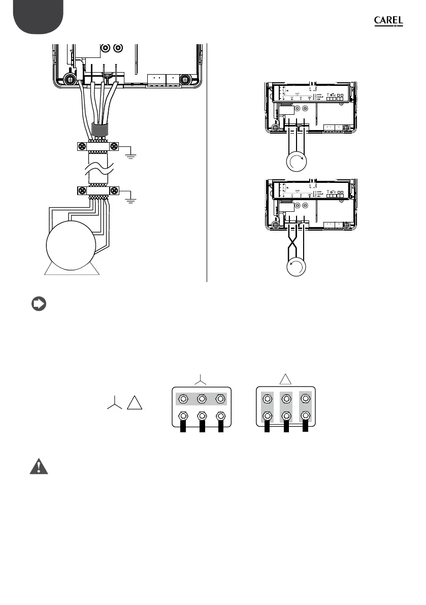
Collegare le fasi del motore in modo da ottenere il senso di
rotazione desiderato: per invertirlo scambiare tra loro due
li U, V, W come descritto nella gura seguente.
3 4 5 6 7
STO
A B
cut this area and access to DIP switches
to set the ID (network) address
3 4 5 6 7
STO
A B
cut this area and access to DIP switches
to set the ID (network) address
M
M
Fig. 3.k Fig. 3.l
Nota: la maggior parte dei motori asincroni sono costruiti per operare con doppia alimentazione. Questo è
indicato nella targhetta del motore. La tensione operativa è normalmente selezionata durante l’installazione del
motore selezionando la connessione a stella o triangolo.
La connessione a stella dà sempre la tensione maggiore tra le due. I valori tipici sono:
/
400V/230 V
W
Fig. 3.m
Attenzione: non aprire e chiudere un interruttore di circuito posto tra il drive e il motore quando il drive è in
funzione (RUN).
Ingresso digitale di sicurezza STO
Collegare i due morsetti dell’ingresso digitale di sicurezza “Safe Torque O” al contatto pulito normalmente chiuso di
un dispositivo di sicurezza, per esempio un pressostato di massima pressione (disegno Ref. A). Quando il contatto è
aperto il funzionamento del drive è interrotto, bypassando il controllo software.
stella triangolo
 Loading...