18
ENG
µchiller +0300053EN rel. 2.2 - 14.12.2021
Installation
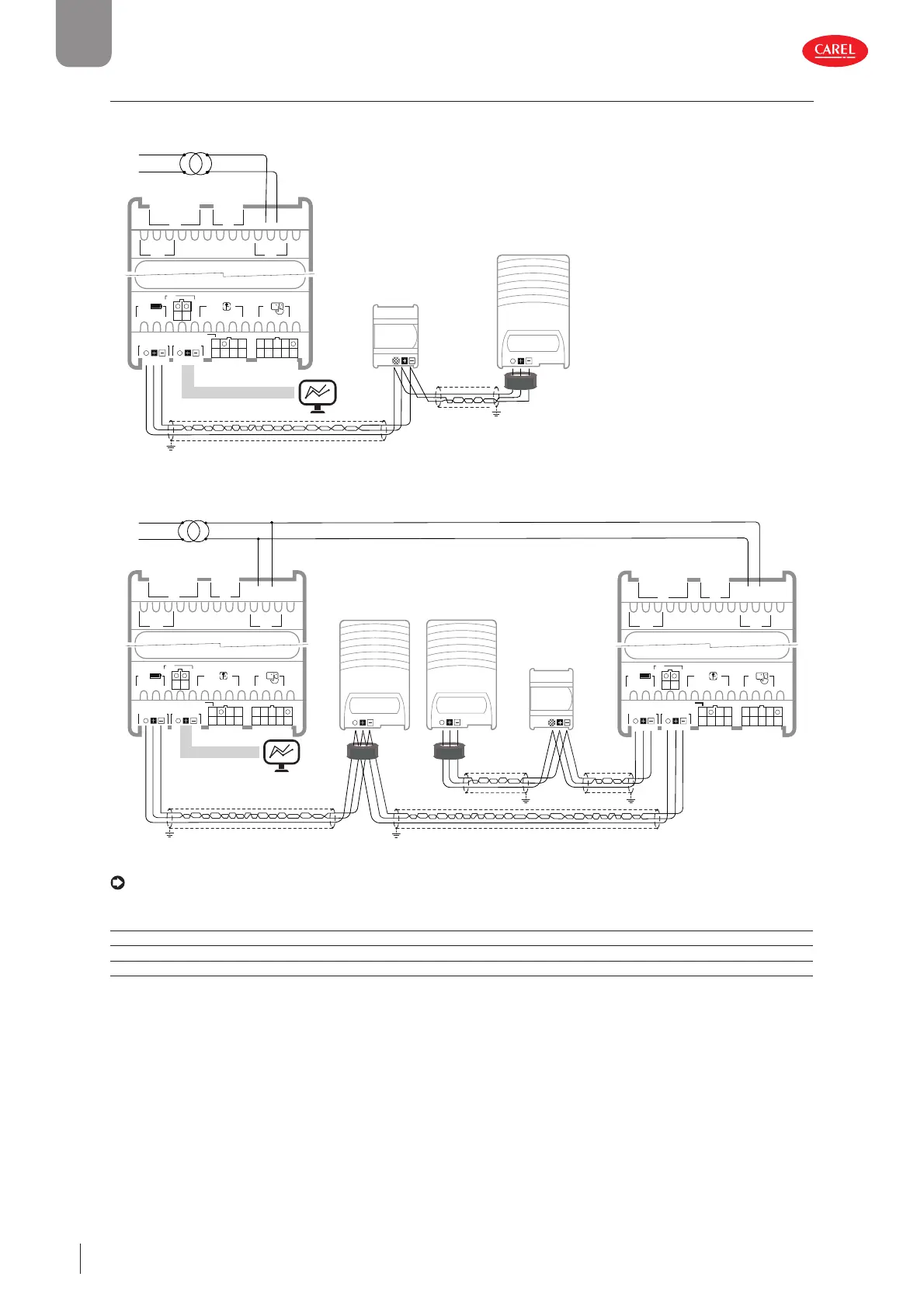
2.10 Connection to Power+ (for BLDC)
For the serial connection between the controller and the Power+ speed drive, see the specifi c manual. Also see the following
diagrams.
J4 BMS
J3
J2
J5 FBus
S1 S3 5V
S2Y2
Y1ID1
ID2
ID3ID5
ID4S4
S6 +V
VL
S5
J1
J7
G0 G
J6
C
C
NO1
NO2
NO3
NO4
NO5
J8J10
J14
J9
S7
ID6
J11
C
NO6
L
N
power+
speed drive
shield
EVD
evolution
shield
Fig. 2.p
L
N
power+
speed drive
shield
EVD
evolution twin
shield
power+
speed drive
shield
shield
Master Slave
1
2
J4 BMS
J3
J2
J5 FBus
S1 S3 5V
S2Y2
Y1ID1
ID2
ID3ID5
ID4S4
S6 +V
VL
S5
J1
J7
G0 G
J6
C
C
NO1
NO2
NO3
NO4
NO5
J8J10
J14
J9
S7
ID6
J11
C
NO6
J4 BMS
J3
J2
J5 FBus
S1 S3 5V
S2Y2
Y1ID1
ID2
ID3ID5
ID4S4
S6 +V
VL
S5
J1
J7
G0 G
J6
C
C
NO1
NO2
NO3
NO4
NO5
J8J10
J14
J9
S7
ID6
J11
C
NO6
Fig. 2.q
Notice: if connecting Power+ (for BLDC) and EVD evolution, the connection parameters are not confi gurable, and must be
set as shown in the table.
Device Address Network settings Baudrate
Power+ speed drive 1 1 8 - NONE - 2 19200
Power+ speed drive 2 1 8 - NONE - 2 19200
EVD evolution 198 8 - NONE -2 19200
Tab. 2.e
 Loading...


