20
ENG
µchiller +0300053EN rel. 2.2 - 14.12.2021
Installation
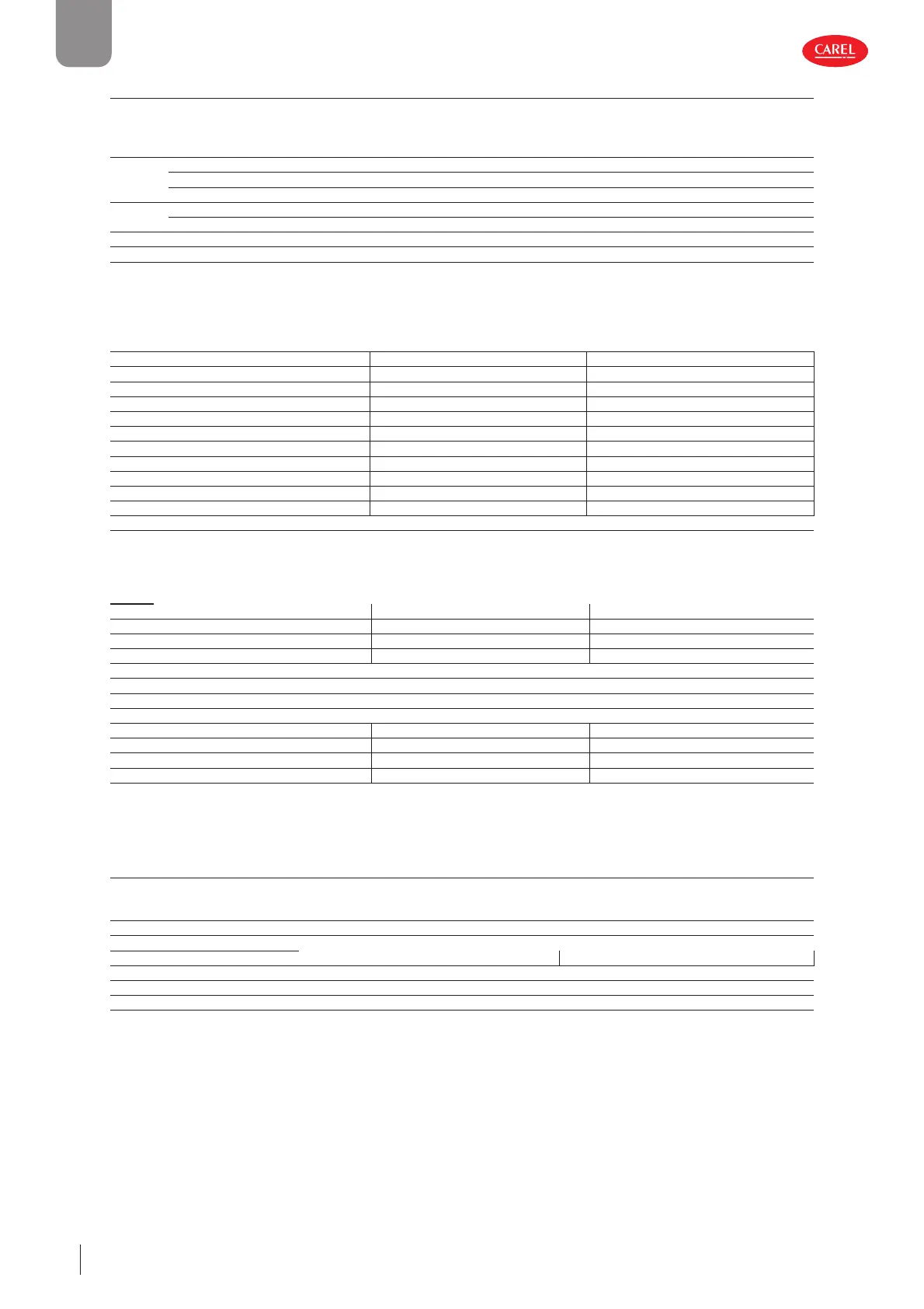
2.12.1 Analogue inputs
The analogue inputs on µChiller Legacy are divided into four groups, according to the type of sensor connected. The groups and
the list of parameters used to confi gure the diff erent analogue inputs are shown below:
Group Sensor Master con g. parameter Slave con g. parameter
GRP1 S1 HC31 HC41
S2 HC32 HC42
S3 HC00 HC43
GRP2 S4 HC34 HC44
S5 HC35 HC45
GRP3 S6 HC03 HC05
GRP1* S7* HC04* HC47
Tab. 2.g
(*) available only on DIN version
The meanings assigned to the analogue inputs according to the various groups for the Master controller (circuit 1) are as follows:
Value GRP1 GRP2 GRP3
0
Source water delivery temp. Source water delivery temp. Source water delivery temp.
1
Outside temperature Outside temperature Outside temperature
2
Discharge temperature circuit 1 Discharge temperature circuit 1 Remote set point
3
Condensing temperature circ. 1 Condensing temperature circ. 1 Discharge temperature circuit 1
4
Suction temperature circ. 1 Suction temperature circ. 1 Condensing temperature circ. 1
5
Evaporation temperature circ. 1 Evaporation temperature circ. 1 Suction temperature circ. 1
6
System water return temperature Condensing pressure circ. 1 Evaporation temperature circ. 1
7
System water delivery temp. Evaporation pressure circ. 1 Condensing pressure circ. 1
8
System water return temperature Evaporation pressure circ. 1
9
System water delivery temp. System water return temperature
10
System water delivery temp.
11 System water delivery temp.
Tab. 2.h
The meanings assigned to the analogue inputs according to the various groups for the Slave controller (circuit 2) are as follows:
Value GRP1 GRP2 GRP3
0
Not used Not used Not used
1
Source water delivery temp. Source water delivery temp. Source water delivery temp.
2
Outside temperature Outside temperature Outside temperature
3
Discharge temperature circuit 2 Discharge temperature circuit 2 Remote set point
4 Condensing temperature circ. 2 Condensing temperature circ. 2 Discharge temperature circuit 2
5 Suction temperature circ. 2 Suction temperature circ. 2 Condensing temperature circ. 2
6 Evaporation temperature circ. 2 Evaporation temperature circ. 2 Suction temperature circ. 2
7 Common delivery water temperature Condensing pressure circ. 2 Evaporation temperature circ. 2
8
Evap. water delivery temp. 2 Evaporation pressure circ. 2 Condensing pressure circ. 2
9
Common water delivery temperature Evaporation pressure circ. 2
10
Evap. water delivery temp. 2 Common water delivery temperature
11
Evaporator 2 water outlet temperature
Tab. 2.i
2.12.2 Digital inputs
Below is the list of parameters used to confi gure the digital inputs:
Digital input Master con guration parameter Slave con guration parameter
ID1 HC14 HC16
ID2 HC15 HC17
ID3
High pressure switch circ. 1 High pressure switch circ. 2
ID4 HC06 HC09
ID5 HC07 HC10
ID6* HC08* HC11
Tab. 2.j
(*) available only on DIN version
 Loading...


