67
ENG
µchiller +0300053EN rel. 2.2 - 14.12.2021
Functions
5.13 Source fans
On units with two circuits, Chiller manages the source (condenser) either separately (independent air circuits) or with one com-
mon air circuit, by setting a parameter: when there is a common air circuit, fan 1 works based on the higher request between
circuit 1 and 2.
User Code Description Def Min Max UOM
S S064 Type of source air circuit - 0 = Independent 1 = Common 001-
Below is a table summarising the probes used for controlling the fans in each confi guration:
Circuit
Probes used for control
Chiller Heat pump
1 Condensing press./temp. circuit 1 Evaporation press./temp. circuit 1
2 Condensing press./temp. circuit 2 Evaporation press./temp. circuit 2
Tab. 5.a
The control mode changes based on the operating mode (chiller or heat pump).
5.13.1 Modulating/On-O fans
On the Chiller panel version, analogue output Y1 is the only output available: consequently to control an on-off fan, a CONVO-
NOFF module (Carel) is needed to convert the 0-10 V analogue output into a relay control. On the versions for DIN rail mounting,
relay NO6 is available and can be confi gured as a fan output. On-Off fans then need to be confi gured.
User Code Description Def Min Max UOM
M Hc12 NO6 confi guration - 0=Frost protection 1=Source fan/pump 001-
S S065 Type of source fan 0/1=Modulating/ON-OFF 001-
S S028 Source fan in cooling: set point 30.0 -999.9 999.9 °C
S S029 Source fan in heating: set point 10.0 0.0 99.9 °C
S S031 Source fan in cooling: set point at start-up 45.0 0.0 999.9 °C
S S032 Source fan: delay at start-up in cooling 240 0 999 s
S S034 Source fan: diff erential in cooling 15.0 0.0 99.9 K
S S035 Source fan: diff erential in heating 5.0 0.0 99.9 K
S S036 Modulating source fan: min speed value 20.0 0.0 100.0 %
S S037 Modulating source fan: max speed value 80.0 0.0 100.0 %
Tab. 5.b
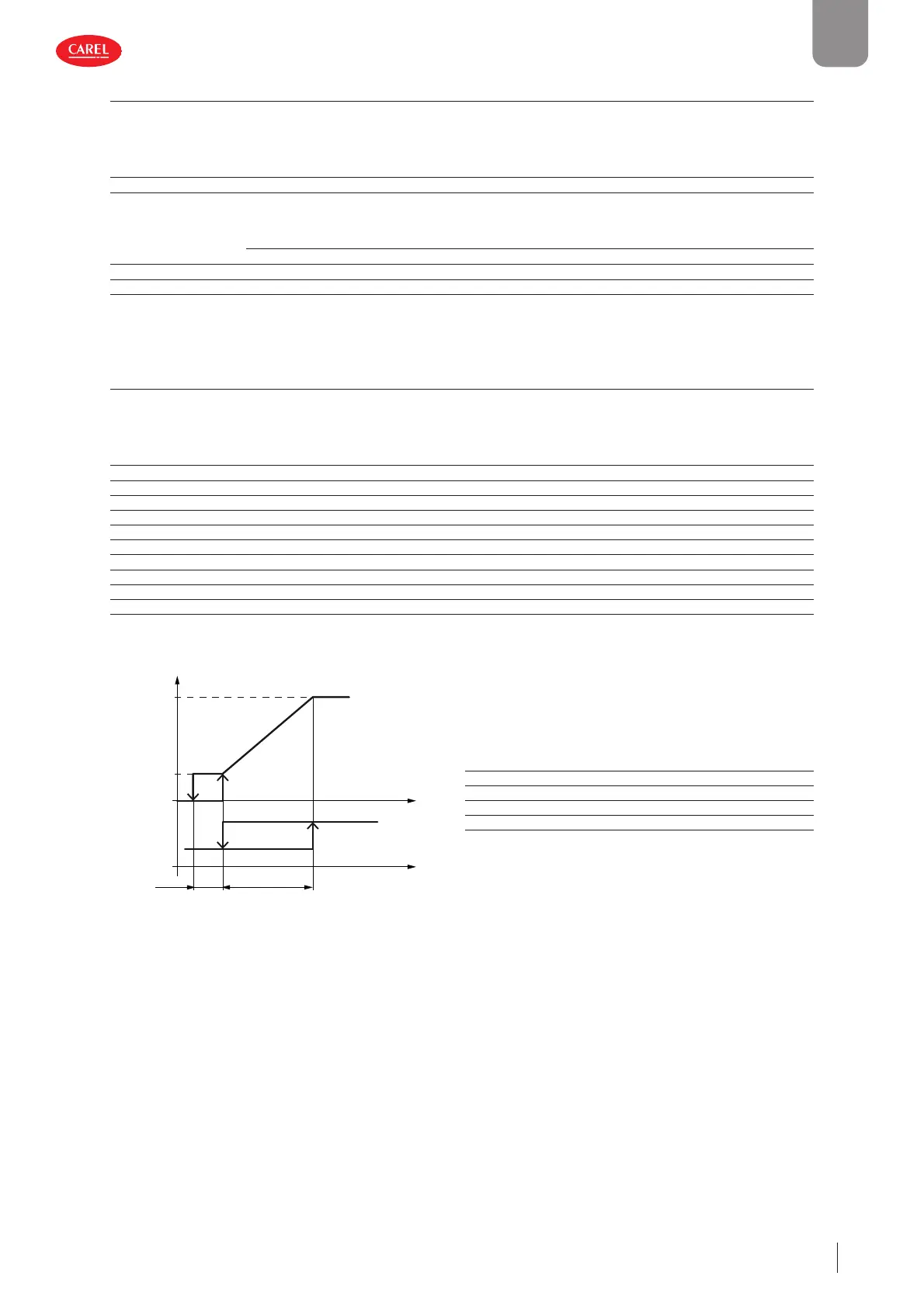
The following diagram shows the two control modes (modulating or on-off ) in chiller operation (cooling):
300053_062_R01
DT5.0
Max speed
Min speed
Inverter
ON/OFF
c (°C)
SP
Key
Max speed Modulating source fan: max speed value
Min speed Modulating source fan: min speed value
SP Control set point
DT Control diff erential
Tc Condensing temperature
Fig. 5.q
 Loading...


