19
ENG
µchiller +0300053EN rel. 2.2 - 14.12.2021
Installation
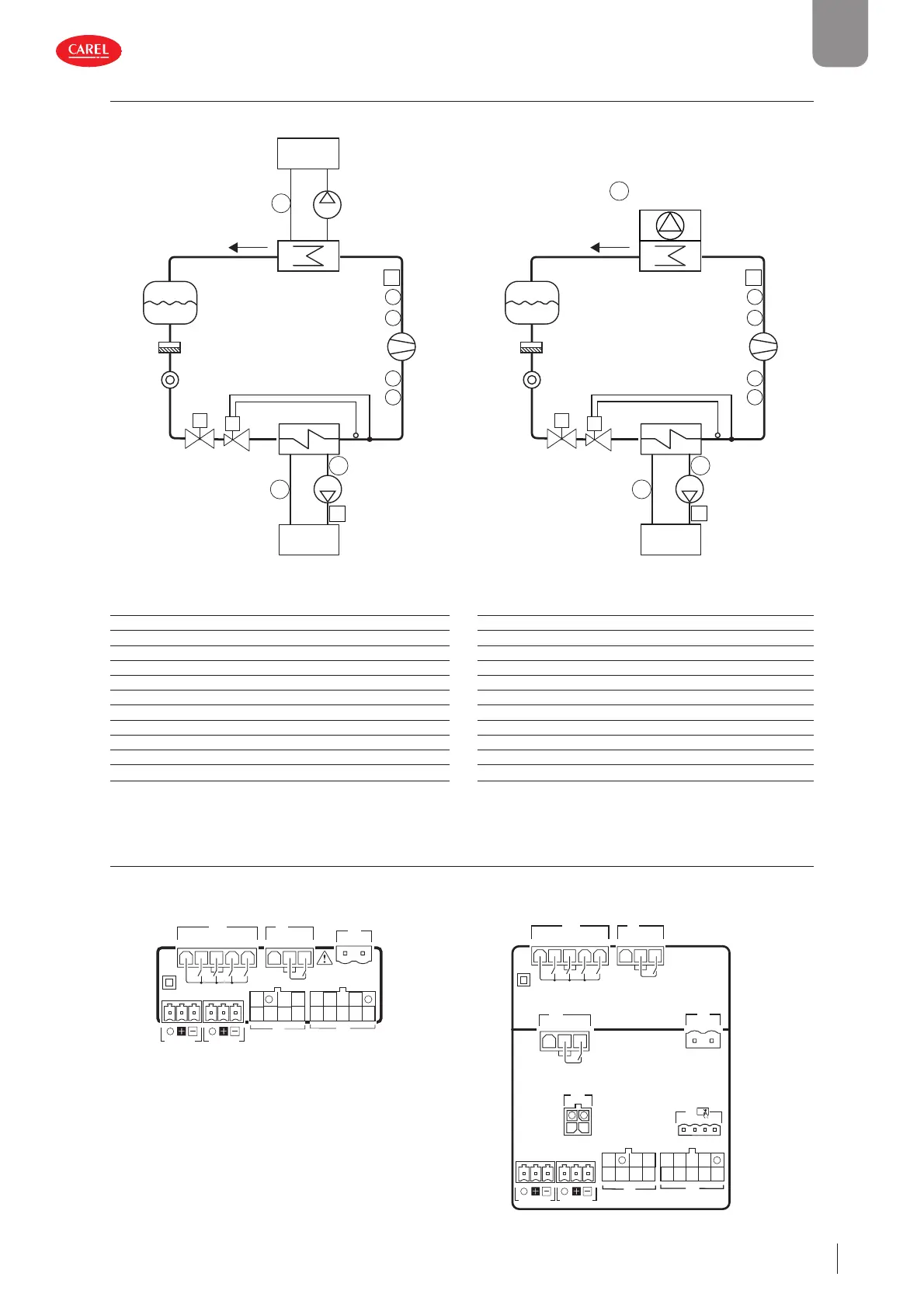
2.11 Positioning of probes/ components
Water-cooled unit Air-cooled unit
E
L
F
SL
CP
PS
PU
T
T3
C
P3
P1
P2
2
1
U
S
T4
F1
T5
VV1
PU
300053_XYZ_R02
E
L
F
SL
CP
T
T3
C
P3
P1
P2
T2
T1
U
T4
F1
T5
VV1
Fig. 2.r Fig. 2.s
Ref. Description Ref. Description
S Source PU User pump
U User PS Source pump
E Evaporator P2 Evaporation pressure probe
F Filter-drier T1 Discharge temperature
L Liquid receiver T2 Suction temperature
CP Compressor P3 High pressure switch
C Condenser T3 Outside air temperature
SL Liquid sightglass F1 User pump fl ow switch
P1 Condensing pressure probe T4 Water delivery temperature (to) user
V Solenoid valve T5 Water return temperature (from) user
V1 Thermostatic expansion valve T6 Water delivery temperature (to) source
Tab. 2.f
2.12 Input/output con guration
Information on how to confi gure the µChiller Legacy inputs and outputs to replace mCH2 and mCH2 SE is shown below.
Panel mounting model DIN rail model (Basic)
J1
J7
G0 G
J6
C
C
NO1
NO2
NO3
NO4
NO5
J2
J3
J4 BMSJ5 FBus
S1 S3 5V
S2Y2
Y1ID1
ID2
ID3ID5
ID4S4
S6 +V
VL
S5
J1
J7
G0 G
J6
C
C
NO1
NO2
NO3
NO4
NO5
J2
J3
J4 BMSJ5 FBus
S1 S3 5V
S2Y2
Y1ID1
ID2
ID3ID5
ID4S4
S6 +V
VL
S5
J11
C NO6
J9
J8
S7
ID6
Fig. 2.t Fig. 2.u
 Loading...


