30
ENG
µchiller +0300053EN rel. 2.2 - 14.12.2021
Installation
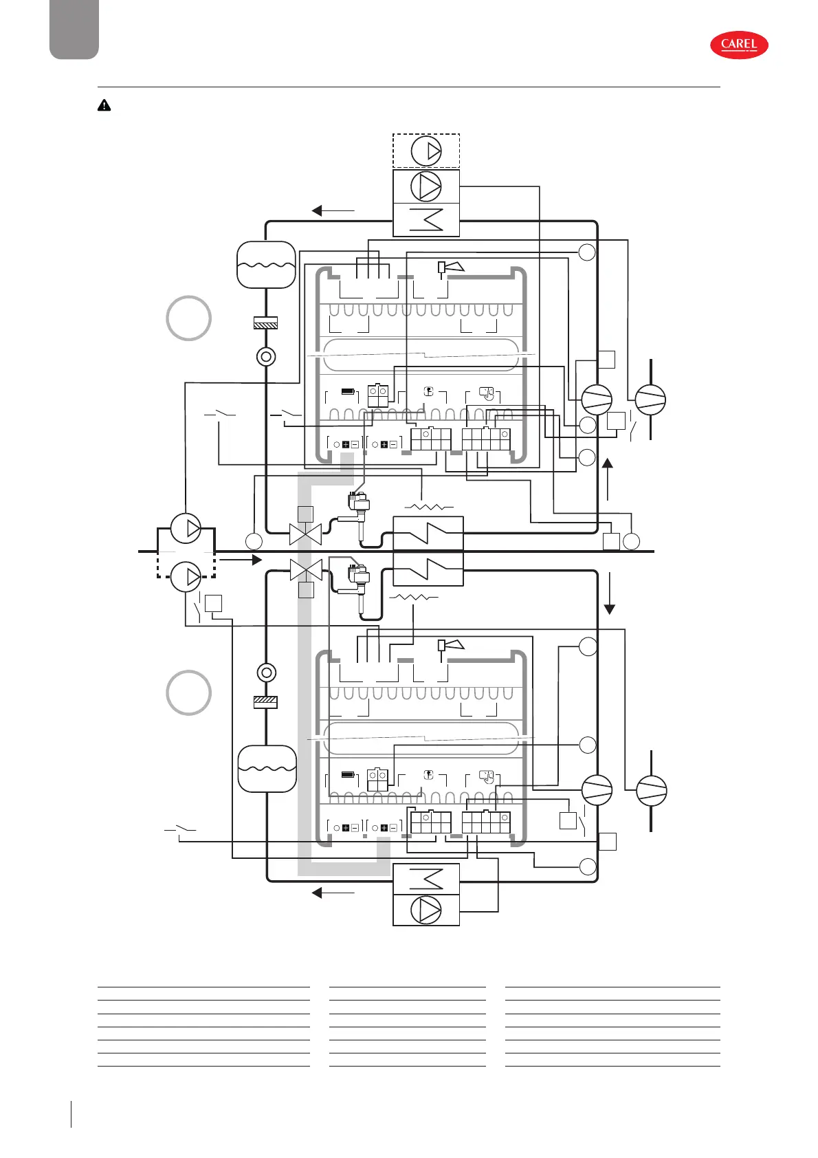
2.13.5 Chillers, On/O compressors and unipolar ExV expansion valve
Important:
The black lines refer to the electrical connections, the grey lines the serial connections between controller
and options (I/O expansion for the second circuit, EVD EVO and Power+).
J4 BMS
J3
J2
J5 FBus
S1 S3 5V
S2Y2
Y1ID1
ID2
ID3ID5
ID4S4
S6 +V
VL
S5
J1
J7
G0 G
J6
C
C
NO1
NO2
NO3
NO4
NO5
J8J10
J14
J9
J11
C
NO6
J4 BMS
J3
J2
J5 FBus
S1 S3 5V
S2Y2
Y1ID1
ID2
ID3ID5
ID4S4
S6 +V
VL
S5
J1
J7
G0 G
J6
C
C
NO1
NO2
NO3
NO4
NO5
J8J10
J14
J9
J11
C
NO6
300053_143_R03
C1
E1
L1
F1
SL1
V1_C1
V1_C2
CP1
P
T
CP2
R
C2
E2
SL2
L2
CP1 CP2
P
P
P
R
T
P
AL
AL
AL1_C2
AL1_C1
P
PU2
PU1
TT
FL
F2
T
1
2
V2_C2 V2_C1
Circuit 1
Circuit 2
2_Set
T
T
S7
ID6
S7
ID6
Fig. 2.z
Ref. Description Ref. Description Ref. Description
C1/C2 Condenser 1/2 SL1/2 Liquid sightglass 1/2 R1/2 Frost protection heater
E1/E2 Evaporator 1/2 F1/2 Filter-drier 1/2 P Pressure probe/pressure switch
V1_C1 Solenoid valve circuit 1 FL Flow switch T Temperature probe/thermostat
V1_C2 Solenoid valve circuit 2 PU1/2 User pump 1/2 CP1/2 Compressor 1/2
V2_C1 Electronic expansion valve circuit 1 L1/2 Liquid receiver 1/2 AL Alarm
V2_C2 Electronic expansion valve circuit 2 2_Set 2nd set point AL1_C1/2 Remote alarm circuit 1/2
Tab. 2.az
 Loading...


