73
ENG
µchiller +0300053EN rel. 2.2 - 14.12.2021
Functions
5.16 Free cooling
5.16.1 Dynamic control gain
This special function manages the balancing of capacity between the free cooling coil and the evaporator: this optimises control
stability and fl uidity.
User Code Description Def Min Max UOM
S U070 Free cooling: hysteresis 1.5 0.0 99.9 K
S U069 Free cooling: activation diff erential 3.0 0.0 99.9 K
S U071 Design free cooling delta T 8.0 0.0 99.9 K
Tab. 5.k
300053_067_R01
D
FC Cap
FC gain
0%
10%
DD
SP
100%
emp
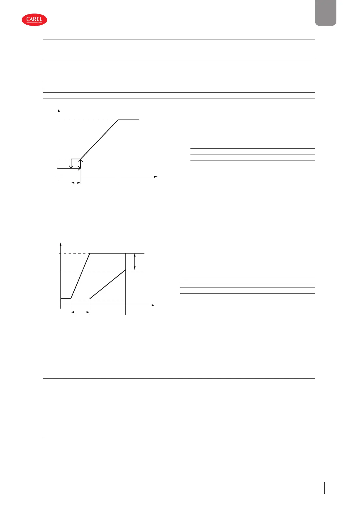
Key
FC Cap Free cooling capacity
DT Hysteresis
SP Activation diff erential
DDT Design free cooling delta T
Temp User return temp. - source temp.
Fig. 5.y
The diagram shows the ideal behaviour of free cooling control (FC) in relation proportionally to its capacity; "Design free coo-
ling delta T" is the temperature diff erence (water inlet - source) needed to cover the rated unit capacity using the free cooling
coil only.
The value obtained - "FC gain" - is used to adapt the control ramp to the various cooling sources, as shown in the fi gure.
300053_068_R01
FC gain
0% 100%
Reg ramp
0%
Reg Cap
100%
FC
ramp
Comp
ramp
FC gain
Key
Reg Cap Control capacity
FC ramp Free cooling control ramp
FC gain Dynamic gain of free cooling control
Comp ramp Compressor control ramp
Reg ramp Control ramp
Fig. 5.z
The result is a perfect balance between the cooling capacities of the free cooling coil and the evaporator, in order to maintain
the same proportionality in all load conditions. In other words, the same percentage of capacity is obtained for the same tem-
perature variation in any load condition.
5.16.2 E ectiveness control
Chiller uses this function to start the compressors when the free cooling coil alone cannot bring the water to the set point,
despite the fact that the source conditions theoretically allow for free cooling operation only. When this occurs, there may be a
malfunction on the devices activated during free cooling; the compressors thus need to be started and free cooling disabled
in order to ensure unit operation.
This situation is signalled by the "Free cooling warning".
5.16.3 Valve anti-block management
To avoid mechanical blocking of the valve, when a position (closed or open) is kept for more than a week, the valve is moved for
30 seconds to the opposite position.
 Loading...


