77
ENG
µchiller +0300053EN rel. 2.2 - 14.12.2021
Functions
Synchronisation (1):
See the previous defrosts.
Compressor stopped to start defrosting (2)
The circuit with the BLDC compressor decreases its capacity to the minimum set value, and then switches off ; on-off compres-
sors are all switched off .
Defrosting (5)
The actual defrosting phase starts: the fans are started at 100% speed to heat the coil and melt the ice that has formed on
the fi ns. Defrosting ends, once the minimum time has elapsed, when the evaporation temperature reaches 2°C, or after the
maximum time. The minimum/maximum defrost time and minimum time between two consecutive defrosts start counting
in this phase.
Dripping (9)
The fans are stopped, waiting for the coil to complete defrosting due to thermal inertia and stop dripping. The dripping time
can be set.
Post-dripping (10)
The fans are started at 100% speed to completely expel any water still on the coil. The post- dripping time can be set. At the
end of the post-dripping phase, the circuit is reactivated in normal heat pump operation.
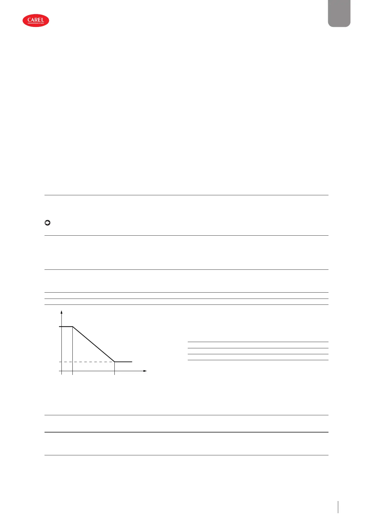
5.17.3 Sliding defrost
As the water vapour content in the air decreases as the outside temperature decreases, the time needed for a layer of ice to
form that requires defrosting increases proportionally as the outside temperature decreases. Consequently, a function has been
added, enabled when the outside air probe is available, which extends the defrost delay time, as shown in the following fi gure.
Note: the outside probe can be connected to inputs S3/S6 (setting: external temperature)
User Code Description Def Min Max UOM
M Hc00 S3 confi guration
0=Not used
1=External temp.
2=Discharge temp.
3=Suction temp.
4=Source water delivery temperature
0 0 3/4 -
M Hc03 S6 confi guration
0=Not used
1=Remote set point
2=External temperature
002-
S S041 Defrost: delay at start-up 30 0 999 min
S S043 Enable sliding defrost: 0/1=No/Yes 001-
300053_072_R01
Delay
D1 x 5
D1
-15°C 7°C
t (s)
Key
Delay Calculated defrost start delay
D1 Defrost start delay
D1 x 5 Maximum defrost delay (5 x D1)
Temp Outside air temperature
Fig. 5.a
5.17.4 Defrost synchronisation
On two-circuit units, the defrosting procedures can be synchronised.
User Code Description Def Min Max UOM
S S053 Defrost synchronisation
0=Independent
1=Separate
2=Simultaneous
002-
Independent
The two circuits start defrosting when the conditions are right, independently of each other. In other words, there is no synchro-
nisation and the circuits can defrost at the same time.
 Loading...


