24
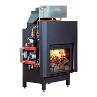
6.21 ELECTRONIC CONTROL UNIT OF THE THERMO FIREPLACE CARINCI SYSTEM AND CARINCI MIX
Control unit instruction manual mod. TC 110-22B-31
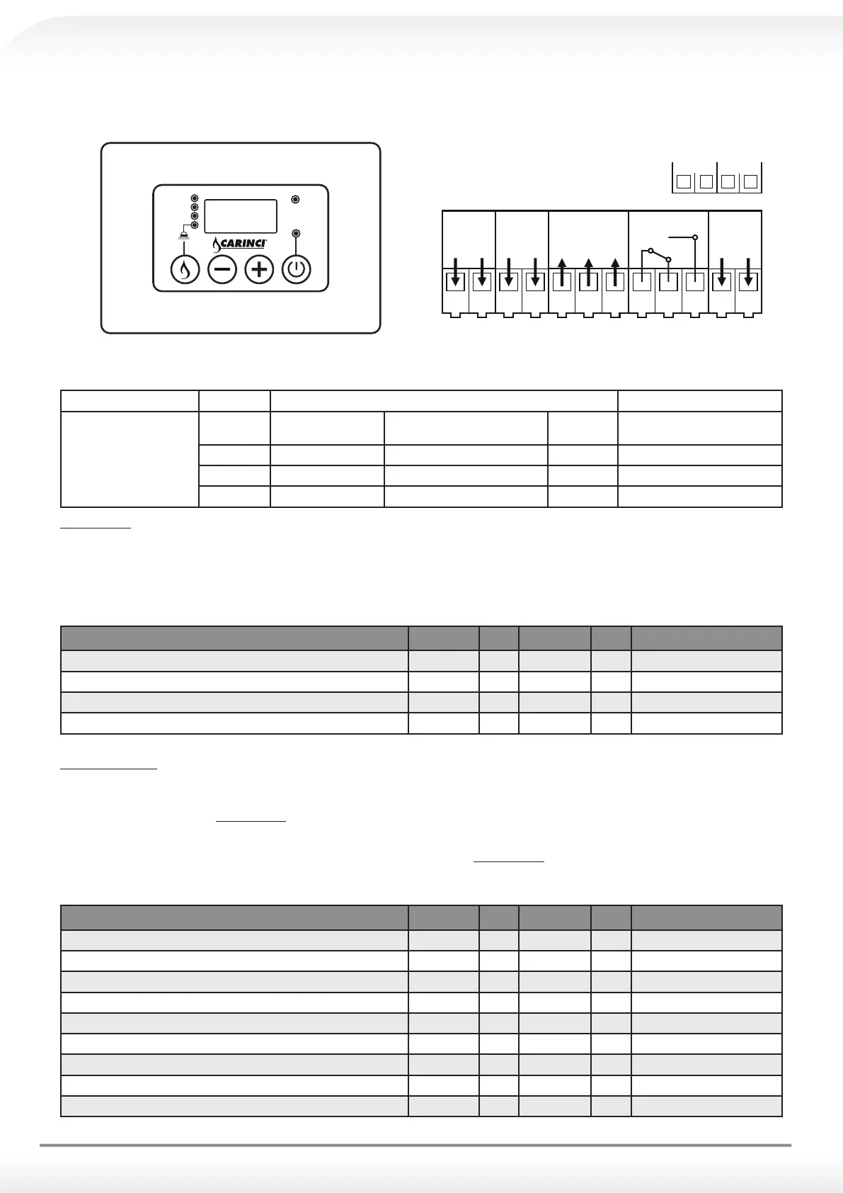
Fig. 1 External appearance and power linkage diagram
INPUTS PROBE
Thermo fireplace probe : Temperature range 0 - 100 ° C
OUTPUTS
PUMP 1
Thermo fireplace
Primary Pump
230 Vac power supply Clips 3(N) - 4 (Fon)
PUMP 2
System Pump 230 Vac power supply Clips 11(N) - 4 (Foff)
VALVE
valve 230 Vac power supply Clips 5(N) - 6 (F
OFF) - 7 (FON)
AUX
Boiler Enabling Free contacts exchange clips 8(COM) - 6 (NC) - 7 (NO)
MAIN Menu
By pressing and holding for about 5 secs P1 button (MENU) it is possible to scroll set thermostats values signalled by the flashing of the respective
LED associated.
For editing:
• Navigate to the value of the thermostat to modify;
• Use the buttons P3 (+) and P2 (-) to increase/decrease the value;
• To save changes wait about 5 secs. or scroll through the values with the P1 button (MENU)
MAIN Menu Parameters Symbol Min Factory Max Installed values
Thermostat PUMP 1 [°C]
A 07
20
50
85
Thermostat PUMP 2 [°C]
A 04
20
50
85
Thermostat VALVE [°C]
A 05
20
42
85
Thermostat AUX [°C]
A 06
20
50
85
INSTALLER Menu
The access to this menu is LIMITED TO TECHNICIANS OR TRAINED PERSONNEL, since some parameters, if modified, can
make the product not anymore suitable for the application in use.
• To access the menu, press simultaneously P1(MENU) P4 (ON/OFF) buttons for about 5 seconds;
• To scroll through the parameter labels use P3 (+) and P2 (-) buttons;
• To display the parameter value, press P1(MENU) button;
• To change the value press P3 (+) and P2 (-) buttons and P1(MENU) button simultaneously;
• To redisplay the list of parameters and store press P1(MENU) button;
• To exit and save wait approximately 5 seconds.
INSTALLER Menu Parameters Symbol Min Factory Max Installed values
Activation thermostat ALARM function [°C]
A 01
85
90
99
SAFETY thermostat [°C]
A 02
20
85
90
ANTIFREEZE Activation thermostat [ICE] [°C]
A 03
4
6
8
Hysteresis thermostat PUMP 1 [°C]
i 07
1
2
20
Hysteresis thermostat PUMP 2 [°C]
i 04
1
2
20
Hysteresis thermostat VALVE [°C]
i 05
1
2
20
Hysteresis thermostat AUX [°C]
i 06
1
2
20
ANTI-LOCK timer [h]
t 01
1
168
255
ANTI LOCK pump activation time [sec]
t 02
0
20
99
LINEA
230 Vac
POMPA
230 Vac
VALVOLA
230 Vac
123456 7
AUX
8910
FNFFon
POMPA 2
230 Vac
11 12
FFonNFo Fon
SONDAFLUX
Pompa 1
Pompa 2
Valvola
Acqua
Plus
Aux
Off
www.termocaminicarinci.it
IL TERMOCAMINO INNOVATIVO