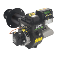
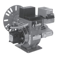
Model 201CRD & 301CRD Advanced oil burners — Instruction manual
Carlin part number MN2301 Rev. 04/12/04
– 22 –
5. Adjustment and verification
Adjust burner using test instruments
1. Operate burner for 15 minutes before making final adjustments using test
equipment.
2. Check for leaks in fuel piping.
Inspect fuel piping system for leaks. Repair any leaks to avoid
fire hazard from oil leakage or combustion problems due to
air infiltration into oil.
3. Inspect flame
• Look at flame through appliance combustion chamber observation port.
The flame should be well-defined and should not impinge on any appliance
surface. (If you make air changes later, inspect the flame again.)
Do not attempt to confirm combustion simply by inspecting
the flame visually. You must use combustion test instruments.
Failure to properly verify/adjust combustion could allow unsafe
operation of the burner, resulting in severe personal injury,
death or substantial property damage.
4. Insert test probe into vent sample opening to sample flue products.
5. With the burner equipped with the correct oil nozzle, combustion head
setting and air band setting, the flue products will usually contain between
11% and 12% CO
2
(5.9% and 3.8% O
2
) and zero (Bacharach) smoke.
6. Use combustion test equipment to verify that burner is properly set up for
your installation, within the range listed in Table 3. Appliances with positive
pressure in the chamber may require a wider air opening. See appliance
instructions for details. Verify/adjust settings by testing with instruments.
a. Check smoke. It should be zero on the Bacharach scale.
b. Set the appliance flue damper or barometric draft regulator so the draft or
pressure in the vent complies with the appliance manufacturer’s instruc-
tions.
c. If no draft setting information is available, set the draft to –0.01 to –0.02
inches w.c. at the appliance flue outlet.
Heating units designed for natural draft operation are normally
set for a slightly negative pressure, usually –0.01 to –0.02
inches w.c. draft at the combustion chamber test port. Ap-
pliances designed for forced draft (positive pressure in the
chamber) must be air-tight to prevent exfiltration of harmful
combustion products. Failure to properly set draft for the
appliance could result in severe personal injury or death.
d. Check percent of CO
2
(or O
2
). Fine tune the burner, if necessary, by slightly
adjusting the head position for more or less air.
e. Each time you change the burner air band or combustion head setting,
you will have to check and possibly adjust the draft.
f. Recheck smoke (should be zero) and flue or chamber pressure/draft (adjust
if necessary and retest).
All installations should be checked after one to two weeks of
operation to ensure the appliance/burner units are operating
correctly.
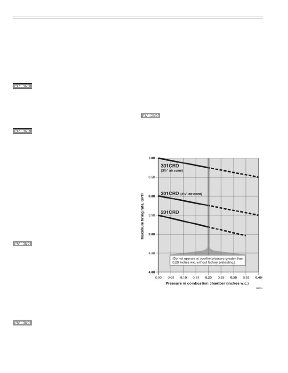
Figure 22 Maximum firing rate decreases as overfire pressure
increases
Firing against positive overfire
pressure
1. Burner rating maximum inputs are based on operation with zero to slightly
negative pressure overfire, typically 0.01 to 0.03 inches w.c.
2. When a burner is applied to an appliance that operates with a higher pres-
sure overfire, the maximum firing rate decreases because the maximum
available air flow from the burner blower decreases.
3. Read the graph below in Figure 22 to find the maximum burner firing rate
at positive overfire pressures.
Do not apply 201CRD or 301CRD burners at positive overfire
pressure higher than shown in Figure 19 unless the applica-
tion has been factory pretested.