Model 201CRD & 301CRD Advanced oil burners — Instruction manual
Carlin part number MN2301 Rev. 04/12/04
– 6 –
Verify combustion chamber
Chamber dimensions and construction
• If retrofitting the burner to an appliance, install the burner in accordance
with the appliance instruction manual, when available. If no specific
application data is available from the appliance manufacturer, read the
guidelines below to check whether the burner is likely to work acceptably
in the application.
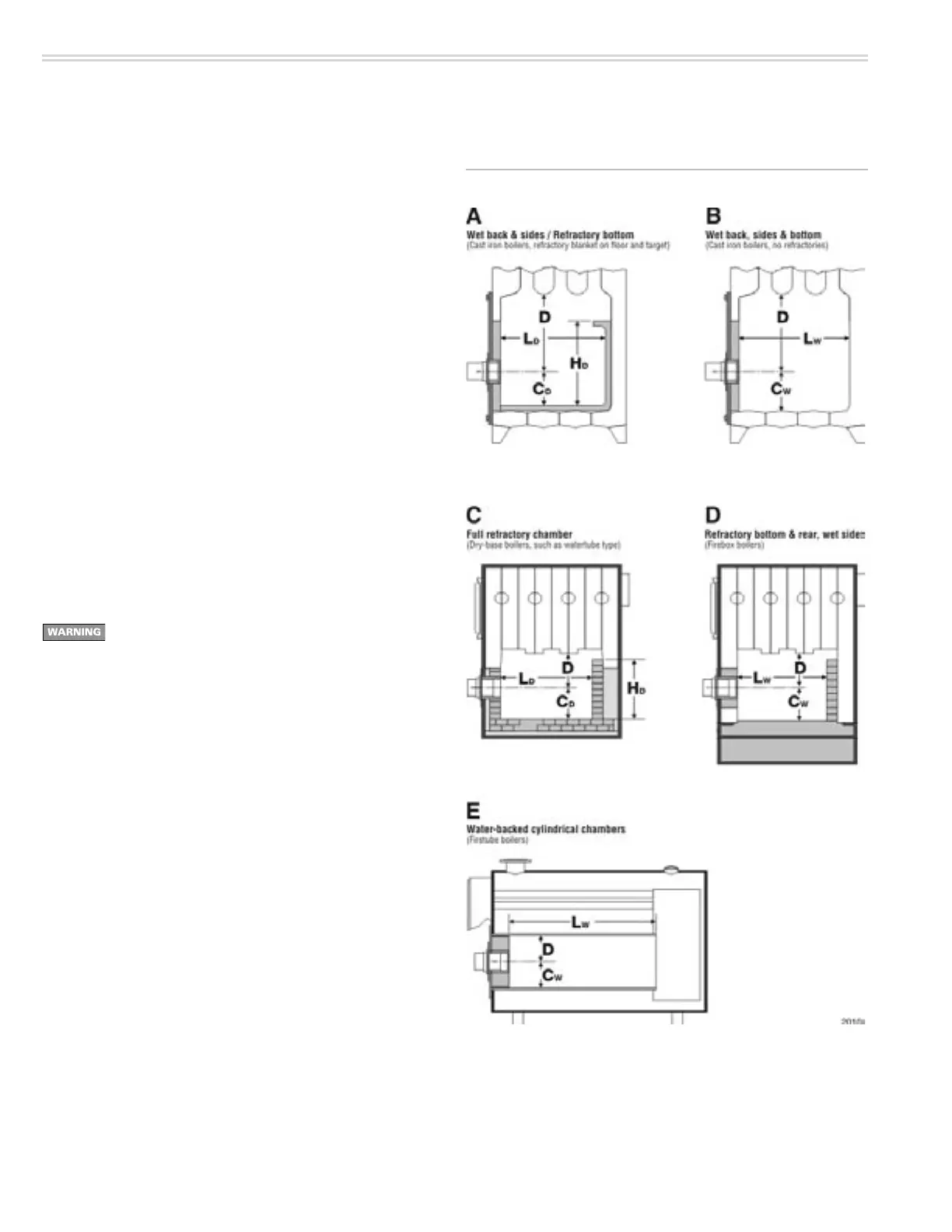
• Illustrations A to E in Figure 1 show different chamber configurations, with
and without refractory linings. The chamber dimensions listed in Table 3
depend on whether the chamber is lined or water-backed, as shown.
• Do not attempt to fire the burner in a chamber with dimensions smaller
than shown in Table 3 unless the application has been specifically tested
and listed by the appliance manufacturer and/or Carlin.
• Chambers with dimensions larger than shown in Table 3 should not have
much effect on combustion/performance.
General guidelines
• Clean all appliance flues and heating surfaces thoroughly, removing all
soot and scale.
• Seal all joints and gaps using furnace cement to prevent excess air
infiltration.
Read the WARNING on page 26 before handling or applying
ceramic fiber materials.
Using chamber linings
• When using refractory liners or lightweight chambers, use insulating-type
refractory rated 2600°F minimum, or as specified by the appliance manu-
facturer.
• You must install a target wall liner if flame length is close to the length of
the chamber.
• Use a floor liner when possible. The floor liner will improve firing in most
applications. Extend floor liner 3 to 4 inches up the side walls.
• Target wall liners — Extend target wall liners at least 3 to 4 inches above
the center of the flame corbel the top 1½ to 2½ inches deep.
• Use preformed chamber liners when available. Lining the floor and target
wall water-backed combustion chambers with lightweight insulating refrac-
tory will accomplish the same.
• When converting coal-fired units, install a combustion chamber in the ashpit
area, or fill the ashpit with sand up to 2 inches above the “mud ring” of the
boiler (firing through the door). Install a lightweight refractory liner on the
target wall as in Figure 2D.
Figure 1 Combustion chamber configurations, typical
2. Prepare site • assemble burner • mount burner (continued)