Carlyle Compressor Div. P O Box 4808 Syracuse, NY 13221
Phone: 800-462-2759 Fax: 315-432-3274
8
Energized whenever the discharge temperature limit is exceeded (see Table 2).
Typically the LiqM and LiqD outputs are wired in parallel with the motor cooling valve.
Thus, the motor cooling valve is energized whenever the motor or discharge
temperature limits are exceeded (see Appendix B for wiring schematic).
Optionally this output could energize a separate liquid injection valve for discharge
temperature control, injecting liquid refrigerant directly into the rotors for discharge
temperature control. Typically, a temperature activated liquid injection valve (strapped to
discharge line) is used for discharge temperature control.
See the Screw Compressor Application Guide for supplemental (in addition to motor
cooling valve) liquid injection requirements.
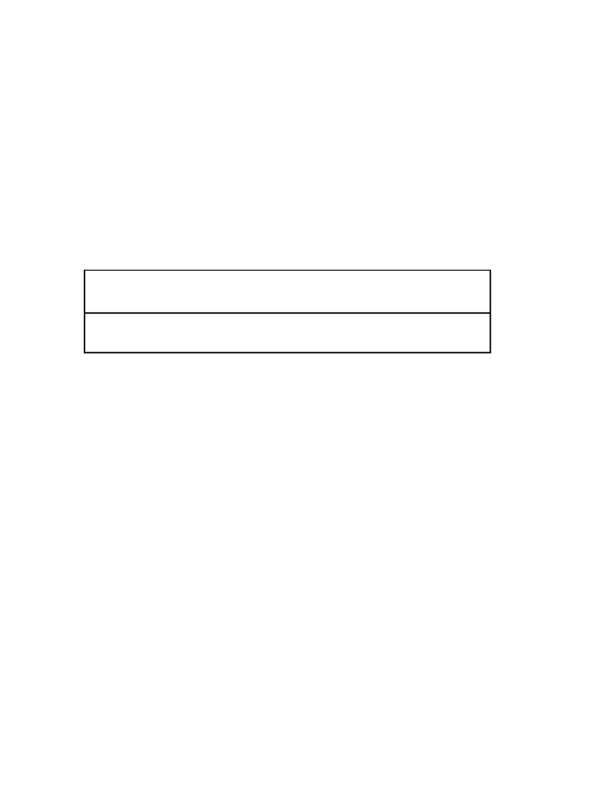
Table 2. Temperature Control Limits
Injection
On
°F (°C)
Injection
Off
°F (°C)
Shutdown
Temp
°F (°C)
Reset
Temp
°F (°C)
Discharge Temperature 205 (96) 190 (88) 230 (110) 200 (93)
Motor Temperature 180 (82) 165 (74) 240 (116) 200 (93)
Unloading (Motor) N/A N/A 220 (104) 205 (96)
UNL Unloader Coil Output
All 05T and 06T screw compressors are supplied with one step of unloading. Control of
the unloading function is not accomplished by the module, but is controlled externally by
a rack controller or pressure switch wired in series with the UNL output. The module has
a 30 second time delay before energizing the unloader output, insuring the compressor
starts unloaded. The compressor is loaded when the unloading coil is energized.
OIL Oil and Economizer Solenoid Output
Energized during compressor operation and is de-energized when it is shut off. The oil
line and economizer line solenoid valves should be connected in parallel to this output
as they are also sequenced on compressor Start/Stop.
It is critical that oil be supplied to the compressor whenever it is running and not supplied
when it is off. Similar concerns exist regarding the flow of refrigerant through the
economizer line. This output insures this functionality.
VI VI Coil Output
All refrigeration duty 05TR and 06TR screw compressors are supplied with VI control.
The Vi valve (stem located at the 3 o’clock position on the outlet casing) controls the
point at which refrigerant exits the rotors. The Vi valve is energized (hi Vi) when the
compression ratio is above 5:1, and de-energized (low-Vi) when the compression ratio
drops below 5:1. The module continuously monitors the operating pressure ratio and

 Loading...

