Carlyle Compressor Div. P O Box 4808 Syracuse, NY 13221
Phone: 800-462-2759 Fax: 315-432-3274
14
Appendix C – Sensor Wire Grounding
In order to avoid electrical noise on the signal input wires it is important to use shielded
cable (pressure transducer harnesses included in the module package are shielded) for
all of the pressure and temperature sensor inputs, and to properly ground them as
discussed below.
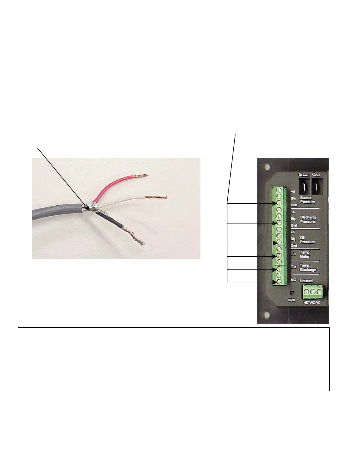
The picture below shows the wiring for the 3 wire pressure transducers. The same
procedure should be used with the 2 wire temperature inputs with the drain wire being
wrapped around the ground wire, which is the bottom wire for the temperature inputs.
Drain wire - should be wrapped around the ground wire and
inserted into the signal ground input (see right)
Pins: 3, 6, 9, 11, 13 and 15
(counting from the top) are
all Ground Inputs
Additional Notes
1. Each sensor (pressure transducers and thermistors) should be run in separate shielded cables, with the
drain wire wrapped around the ground* wire and both connected to the ground input.
2. The shielded cable drain wire should only be connected at the module end (i.e. not grounded at the sensor
end).
* The ground wire is the black wire for the pressure transducer’s and is whatever wire is connected to the
ground input (bottom input) for the thermistors.

 Loading...

