2
CONTENTS
Page
SAFETY CONSIDERATIONS . . . . . . . . . . . . . . . . . . . 1
INTRODUCTION . . . . . . . . . . . . . . . . . . . . . . . . . . . . . 2
INSTALLATION . . . . . . . . . . . . . . . . . . . . . . . . . . . . . . 3
Step 1 — Complete Pre-Installation Checks . . . . . . 3
• IDENTIFY UNIT
• INSPECT SHIPMENT
Step 2 — Mount the Pumpout Unit . . . . . . . . . . . . . . 3
• MOUNTING ON THE CHILLER
• FLOOR MOUNTING
Step 3 — Rig the Storage Tank . . . . . . . . . . . . . . . . . 4
Step 4 — Make Piping Connections . . . . . . . . . . . . . 6
• INSTALL VENT PIPING TO RELIEF DEVICES
Step 5 — Make Electrical Connections . . . . . . . . . . 6
CONTROLS AND COMPONENTS . . . . . . . . . . . . . . 10
Pumpout Unit . . . . . . . . . . . . . . . . . . . . . . . . . . . . . . 10
• CONTROLS
• SAFETY CONTROL SETTINGS
•COMPRESSOR
• CONDENSER
•OIL SEPARATOR
• SUCTION AND DISCHARGE VALVES
Storage Tank . . . . . . . . . . . . . . . . . . . . . . . . . . . . . . 11
•DRAIN VALVE
• DUAL RELIEF VALVES
• PRESSURE GAGE
• LEVEL GAGE
OPERATION . . . . . . . . . . . . . . . . . . . . . . . . . . . . . . . 11
Overview . . . . . . . . . . . . . . . . . . . . . . . . . . . . . . . . . . 11
• REFRIGERANT TRANSFER
• TRANSFERRING LIQUID REFRIGERANT FROM THE
CHILLER COOLER TO THE CHILLER CONDENSER
OR PUMPOUT STORAGE TANK
• TRANSFERRING LIQUID REFRIGERANT FROM THE
CHILLER CONDENSER OR PUMPOUT STORAGE
TANK TO THE CHILLER COOLER
• DISTILLING THE REFRIGERANT
Pumpout and Refrigerant Transfer Procedures . . 12
• PREPARATION
• OPERATING THE OPTIONAL PUMPOUT UNIT (FIG. 9)
MAINTENANCE . . . . . . . . . . . . . . . . . . . . . . . . . . . . . 17
Pumpout Compressor Oil Charge . . . . . . . . . . . . . 17
Storage Tank . . . . . . . . . . . . . . . . . . . . . . . . . . . . . . 17
Ordering Replacement Parts . . . . . . . . . . . . . . . . . 17
TROUBLESHOOTING . . . . . . . . . . . . . . . . . . . . . . . . 17
INTRODUCTION
The 19XR Positive Pressure Storage (PPS) system has been de-
signed to help owners and operators of positive pressure chillers
store R-513A refrigerant during service and repair work. The
19XR system conserves this refrigerant and prevents the release of
excessive amounts of refrigerant into the atmosphere. The proper
use of this equipment minimizes the loss of HFCs.
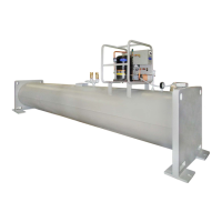
The 19XR PPS system shown in Fig. 1 consists of a pump-out
unit mounted on a storage tank. The pumpout unit is offered as a
free-standing unit that can be used with chillers that have an exist-
ing storage tank or with chillers that have isolation valves that per-
mit built-in refrigerant storage.
The 19XR PPS systems are factory tested and certified to the
American Society of Mechanical Engineers (ASME) pressure
vessel code. The tanks are constructed of certified steel and are
pressure rated at 185 psig (1276 kPa). The PPS storage tank is
equipped with dual relief valves for proper venting per ASHRAE
15 (American Society of Heating, Refrigerating, and Air-Condi-
tioning Engineers) guidelines. An automatic level switch is pre-
wired to the control circuit to ensure proper storage levels.
WARNING
CHECK THE REFRIGERANT TYPE before transferring
refrigerant to the machine. The introduction of the wrong
refrigerant can cause damage or malfunction to this machine.
Operation of this equipment with refrigerants other than those
cited herein should comply with ASHRAE 15 (latest edition).
Contact Carrier for further information on use of this machine
with other refrigerants.
ENSURE that refrigerant is only pumped to or stored in tanks
that are ASME (American Society of Mechanical Engineers)
certified for the pressures appropriate to the refrigerant being
handled.
DO NOT ATTEMPT TO REMOVE fittings, covers, etc.,
while machine is under pressure or while machine is running.
Be sure pressure is at 0 psig (0 kPa) before breaking any
refrigerant connection.
CAREFULLY INSPECT all relief devices, rupture discs, and
other relief devices AT LEAST ONCE A YEAR. If machine
operates in a corrosive atmosphere, inspect the devices at more
frequent intervals.
DO NOT ATTEMPT TO REPAIR OR RECONDITION any
relief device when corrosion or build-up of foreign material
(rust, dirt, scale, etc.) is found within the valve body or mecha-
nism. Replace the device.
DO NOT install relief devices in series or backwards.
USE CARE when working near or in line with a compressed
spring. Sudden release of the spring can cause it and objects in
its path to act as projectiles.
CAUTION
Failure to follow these procedures may result in personal
injury or damage to equipment.
EQUIPMENT should be operated by certified personnel only.
DO NOT STEP on refrigerant lines. Broken lines can whip
about and cause personal injury and damage to the machine.
DO NOT climb over a machine. Use platform, catwalk, or
staging. Follow safe practices when using ladders.
USE MECHANICAL EQUIPMENT (crane, hoist, etc.) to lift
or move inspection covers or other heavy components. Even if
components are light, use such equipment when there is a risk
of slipping or losing your balance.
BE AWARE that certain automatic start arrangements CAN
ENGAGE THE STARTER. Open the disconnect ahead of the
starter in addition to shutting off the machine or pump.
USE only repair or replacement parts that meet the code
requirements of the original equipment.
DOUBLE-CHECK that coupling nut wrenches, dial indicators,
or other items have been removed before rotating any shafts.
DO NOT LOOSEN a packing gland nut before checking that
the nut has a positive thread engagement.
PERIODICALLY INSPECT all valves, fittings, and piping for
corrosion, rust, leaks, or damage.
DO NOT MIX REFRIGERANT from chillers that use differ-
ent compressor oils. Compressor damage can result.
DO NOT re-use compressor oil or any oil that has been
exposed to the atmosphere. Dispose of oil per local codes and
regulations.
DO NOT leave refrigerant system open to air any longer than
the actual time required to service the equipment. Seal circuits
being serviced and charge with dry nitrogen to prevent oil con-
tamination when timely repairs cannot be completed.
 Loading...