14
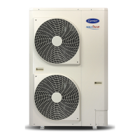
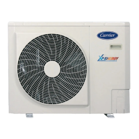
30AW
30AWH__X , 30AWH__NX integrated water circuit
3.3.2 Water connections
Note: The correct dimensioning of the expansion vessel is left to the
installer as a function of the type of plant.
The discharge of the safety valve can be channelled to the outside of the
machine using the pre-cut holes. In this case, it is necessary to provide a
open drain funnel.
Installation
3
Make the plate heat exchanger hydraulic connections with the
necessary components, using material which will guarantee that the
screwed joints are leakproof.
The typical hydraulic circuit diagrams (par. 3.3.3) show a typical water
circuit installation.
For an application with a water circuit, the following recommendations
must be taken into account:
The pump must be tted immediately before of the heat exchanger 1.
and after the connection to the system return (unit without hydronic
module).
*UJTBEWJTBCMFUPJOTUBMMTIVUPòWBMWFTUPBMMPXJTPMBUJPOPGUIF2.
most important circuit components, as well as the heat exchanger
itself. These valves (ball, globe or buttery valves) should produce a
minimum loss of charge when they are open.
Provide unit and system drains and vents at the lowest system point.3.
Install purges in the higher sections of the installation.4.
Pressure ports and pressure gauges should be installed upstream 5.
and downstream of the water pump.
All piping must be adequately insulated and supported.6.
automatic purge valve1.
ow switch2.
safety valve (outlet 1/2’)3.
temperature probe4.
Unit
30 AWH
004 006 008 012 015
Nominal water ow Std l/s 0,20 0,28 0,33 0,58 0,69
Water loop content
for 30AWH__X,
30AWH__NX
Min l 14 21 28 42 49
Max l
According to
expansion vessel installed
Max water loop
pressure
Max kPa 300 300 300 300 300
Filling water
pressure
Min kPa 120 120 120 120 120
Max elevation 30AW
upper
Max m 20 20 20 20 20
4
4
1
2
3
4
4
1
2
3
ATTENTION:
The presence of particles in the water can lead to obstructions in the 1.
heat exchanger. It is therefore necessary to protect the heat
exchanger inlet with an extractable mesh lter. The lter mesh gauge
must be at least 10 mesh/cm^2.
After assembling the system, or repairing the circuit, the whole 2.
system must be thoroughly cleaned with special attention paid to
the state of the lters.
Pump ow rate control is made through a ow control valve, which 3.
must be installed on the delivery pipe during installation.
When water has to reach temperatures below 5°C, or the equipment 4.
is installed in areas subject to temperatures below 0°C, it is necessary
to mix water with inhibited ethylene glycol in suitable quantity.
SM_30AW.indd 14 14-03-2011 14:41:19

 Loading...

