15
30AW
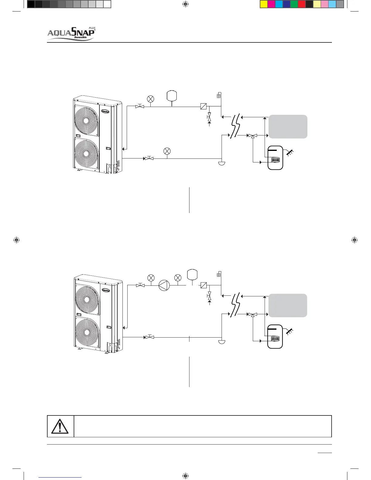
3.3.3 Typical hydraulic circuit diagrams
Hydraulic circuit diagrams for 30AWH___H
Hydraulic circuit diagrams for 30AWH___X and 30AWH___NX
TIVUPòWBMWFT1.
line lter for water (10 mesh/cm^2)2.
pressure gauges3.
lling valve4.
system drain valve (at the lowest points of the circuit)5.
TIVUPòWBMWFT1.
line lter for water (10 mesh/cm^2)2.
pressure gauges3.
lling valve4.
system drain valve (at the lowest points of the circuit)5.
Installation
3
air ushing valve (in the highest parts of the circuit)6.
3-way valve7.
sanitary water accumulation tank8.
inside system9.
air ushing valve (in the highest parts of the circuit)6.
3-way valve7.
sanitary water accumulation tank8.
inside system9.
water circulation pump10.
expansion vessel11.
12
33
10
4
6
1
5
7
8
9
11
1
1
2
3
3
4
6
5
7
8
9
TO PREVENT THE WATER CIRCUIT FREEZING DURING DEFROST OPERATION OR CONTINUOUS COMPRESSOR FREQUENCY
MODULATIONS, BE SURE OF THE MINIMUM RECOMMENDED VOLUME IN THE WATER LOOP
SM_30AW.indd 15 14-03-2011 14:41:21
 Loading...


