10
30RQSY units can be installed inside a building and
connected to a air distribution duct network:
- Air heat exchanger side, at the fresh air suction side for
30RQSY 039 to 078 units
- Fan discharge side at the evacuation side of the treated
air by the unit heat exchanger (30RQSY 039 to 160).
For the precise dimensions of this connection interface please
refer to the dimensional drawings for the units.
Location of the air
temperature sensor
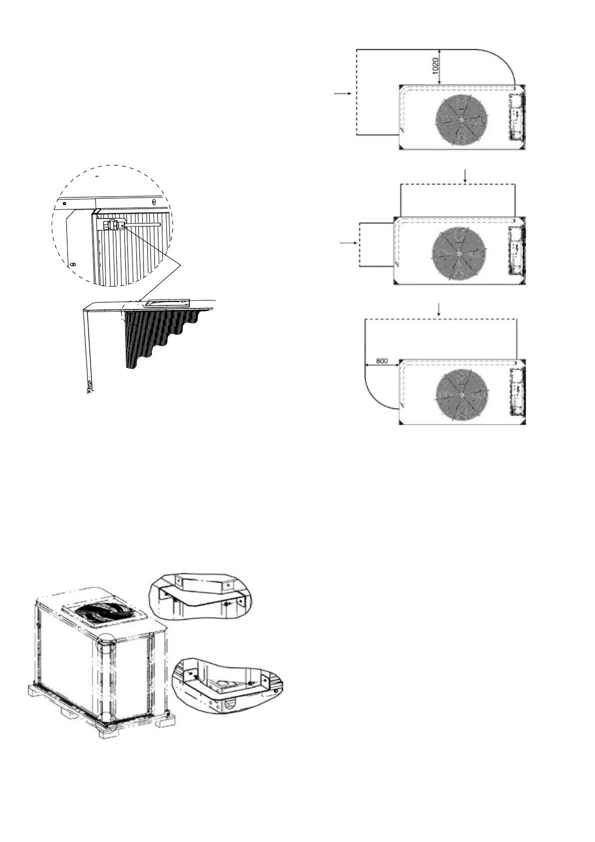
3.2.1 - Standard unit suction connection
30RQSY 039 to 078 units are supplied with a sleeve that
allows connection of an air heat exchanger suction duct.
Provide a removable window on the suction duct to allow
the maintenance of the sensor (see gure above).
For units 30RQSY 050 to 078 the air heat exchanger is on
two unit sides. It is therefore necessary to install two
additional brackets to allow connection of the heat exchanger
suction duct.
These parts are inside the machine and xed to the riser (as
shown on the diagram below) with plastic collars.
Specic connection precautions for sizes 30RQSY 050 to 078
Air inlet
Air inlet
Air inlet
Air inlet
minimum
minimum
3.2.2 - Fan discharge connection
A square ange is supplied mounted on the unit. An available
standard round ange can easily be installed at the fan
discharge, if the installer prefers the use of a round connection
duct.
The unit is supplied with a grille on the discharge side. This
grille has to be removed before connection to the duct system.
It is advisable to make the connection to the duct system
with a exible sleeve. If this recommendation is not observed,
a lot of vibration and noise may be transmitted to the building
structure.