36
Refer to the chapter ‘‘Water connections’’ for all references
points mentioned in this chapter.
The water circulation pumps of unit range have been designed
to allow the hydronic modules to operate at each possible
conditions, i.e. with chilled water temperature differences at
full load from 3 to 10 K.
This temperature difference required between the water inlet
and outlet determines the nominal ow of the system. Use
the specification provided while selecting the unit to
determine the operating conditions of the system.
In particular, collect the data to be used for the control of
the system ow rate:
• Units without hydronic module : the nominal unit
pressure drop. This is measured with pressure gauges
that must be (eld) installed at the inlet and outlet of
the unit (item 21).
• Units with xed speed pumps : nominal ow rate. The
pressure of the uid is measured by sensors at the inlet of
the pump and outlet of the unit (items 7 and 10).The
controls then calculate the ow rate associated with this
pressure difference and display the result on the user
interface. (refer to unit control manual).
• Units with variable speed pumps : the constant pressure
differential control based on readings at the hydronic
module inlet and outlet. The buffer tank module option
is not taken into account.
• Units with variable speed pumps : the control on
temperature difference measured at the heat exchanger
inlet and outlet.
If this information is not available at the start-up of the
system, contact the technical service department responsible
for the installation to obtain them .
These data can be obtained either from the technical
document with unit performance tables for a Delta T° of 5K
at the evaporator, or with the help of the ‘‘Electronic Catalog’’
selection program for all conditions of Delta T° different
from 5 K in the range of 3 to 10 K.
13.1.1 - General information
The nominal ow of the unit will be set using a manual valve
that should be installed on the outlet of the unit (item 19 on
the schematic hydronic circuit). Changing the pressure drop
of the valve allows adjustment of the system ow rate to
achieve the design ow rate.
As the total system pressure drop is not known exactly at the
start-up, it is necessary to adjust the water ow with the control
valve to obtain the specic ow of the system.
13.1.2 - Procedure for cleaning the hydronic circuit
• Open the valve completely (item 22).
• Start-up the system pump.
• Read the pressure drop of the plate heat exchanger as
the difference between the unit inlet and outlet pressures
(item 21).
• Let the pump run for 2 hours consecutively to clean up
the hydronic circuit of the system (presence of
contaminating solids).
• Perform another reading.
• Compare this value to the initial value. A decrease in
the pressure drop value indicates that the lters in the
system need to be removed and cleaned. In this case,
close the Shut-off valves on the water inlet and outlet
(item 19) and remove then clean the lters (items 20 and
1) after draining the hydronic part of the unit (item 6).
• Remove the air from the circuit (items 5 and 17).
• Repeat until the lter remains clean.
13.1.3 - Procedure for controlling the water ow
Once the circuit is cleaned, read the pressures on the pressure
gauges (water inlet and outlet pressure) determine the pressure
drop within the unit (plate heat exchanger + internal pipe
work).
Compare the value obtained with the design value predicted
by the selection software.
If the pressure drop reading is above the specied value, this
indicates that the ow at the terminals of the unit (and hence
in the system) is too high. In this case, close the control valve
and read the new difference in pressure. Repeat as necessary
until the pressure drop corresponding to the design ow rate
is achieved.
NOTE: If the network has an excessive pressure drop in relation
to the available static pressure delivered by the system pump,
the nominal water ow cannot be obtained (lower resulting
ow) and the difference in temperature between the water inlet
and outlet of the evaporator will be increased
To reduce the hydraulic system pressure drop:
• Reduce the pressure drops of individual components
(bends, level changes, valves etc.) as much as possible
• Use the correct pipe diameter
• Do not extend the piping system.
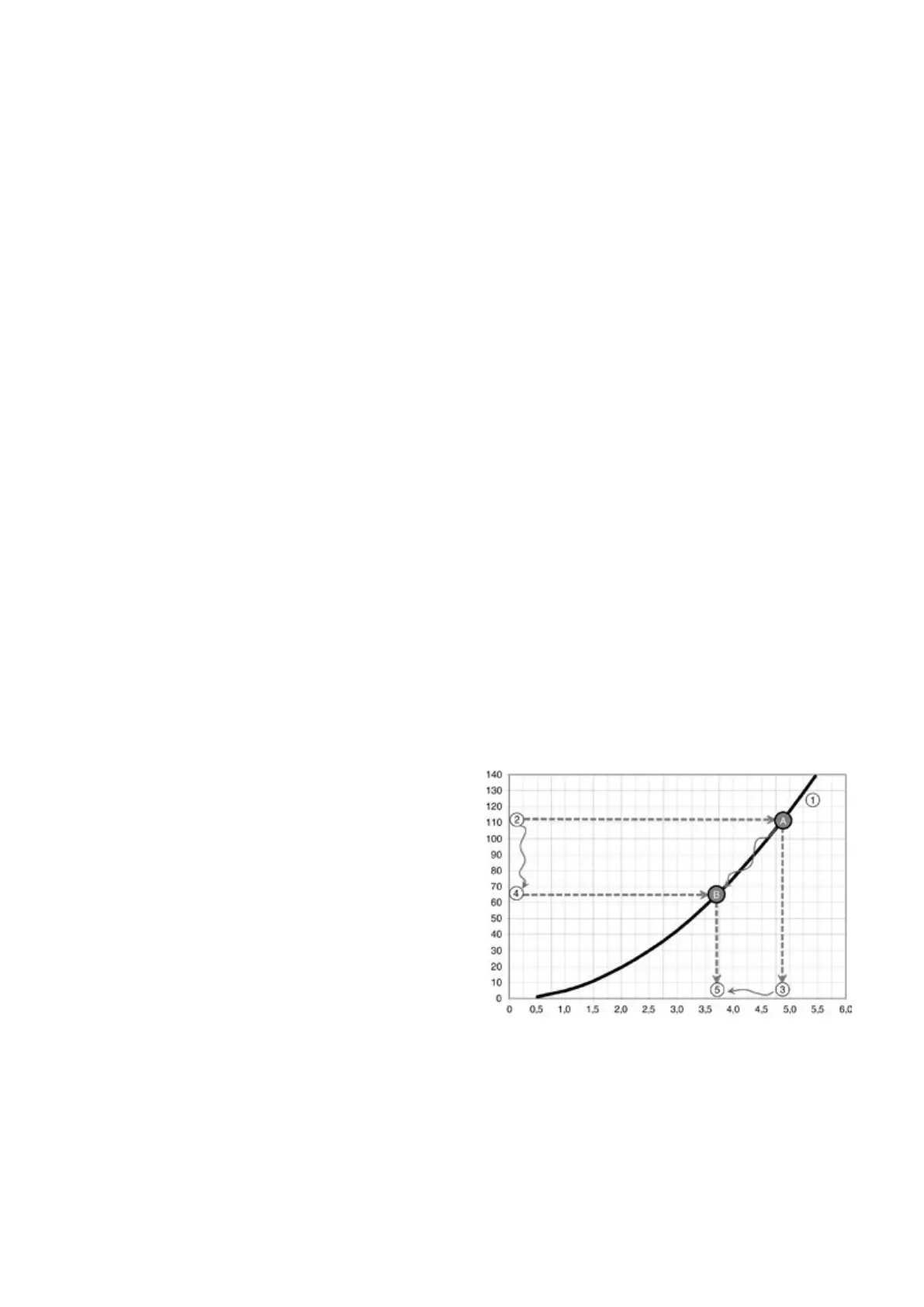
Pressure drop, kPa
A