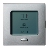
Information Display – The information buttons allow
the bypass controller to display:
• supply airflow pressure
• bypass damper position
• system pressure set point
• duct temperature
The bypass controller continuously displays the system
information corresponding to the last information button that
was pressed. After a bypass controller reset, the information
display indicates the bypass damper position.
NOTE: If the information being shown has been forced by
network software, an "F" will be shown on the display screen
when the data is shown.
NOTE: If the bypass controller is participating in IAQ mode
operation, "IA9" will be displayed on the screen.
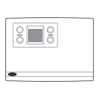
INFORMATION BUTTONS — The bypass controller is
equipped with 4 information buttons which are used to se-
lect the system information to be displayed and to configure
the installer programmable functions of the bypass control-
ler. See Fig. 7. The information buttons display supply air-
flow pressure, bypass damper position, system pressure set
point, and duct temperature.
TEMPERATURE SCALE DISPLAY — Temperature sen-
sor information is displayed by the bypass controller in in-
crements of 0.1 degree Celsius or Fahrenheit when the DUCT
TEMP information button is pressed.
FAHRENHEIT TEMPERATURE DISPLAY — The Fahr-
enheit Temperature Display Option determines whether tem-
peratures are displayed in Celsius or Fahrenheit. The default
is ON. The Fahrenheit Temperature Display Option can be
configured at category 1, option 3.
If the Fahrenheit Temperature Display option is set to OFF,
the bypass controller displays temperature information in the
Celsius scale. If the Fahrenheit Temperature Display is set to
ON, the bypass controller displays temperature information
in the Fahrenheit scale.
PRESSURE SENSOR DISPLAY — The bypass controller
will display pressure sensor information in increments of
0.01 in. wg.
DAMPER POSITION DISPLAY — To display damper po-
sition, the bypass controller divides the position of the by-
pass damper into 16 increments. Full-open is designated as
position 15. Full-closed is designated as position 00.
Bypass Controller Initialization Display — The
bypass controller activates the bypass controller initializa-
tion display when it initially receives power and after reset
is initiated.
The bypass controller will display the rotating lines while
it establishes the bypass damper actuator home position. The
bypass controller will then begin system operation and will
display the bypass damper position.
Alternate Information Display — Allows the by-
pass controller to display additional information. Simulta-
neously press both right or left information buttons, and the
bypass controller will display a sequence of information. The
information displayed is determined by the configuration
setting of Alternate Information. The display can be frozen
by pushing any information button during the display
sequence.
TheAlternate Information option can be set to ON or OFF.
To configure, set category to 7 and option to 2. Use the left
information buttons to toggle the option ON or OFF. The
default is OFF.
When Alternate Information is ON and the Information
Display mode is activated, the bypass controller will display
the following information (if available) in this order:
• (1) zone temperature
• (2) time of day
• (3) security level
• (4) IAQ switch status (digital input)
The information is shown on the top half of the display
screen. The number of the sequence (1 to 4) is shown in the
bottom right corner to help distinguish which piece of in-
formation is being displayed. The numbering is not shown
when theAlternate Information option is turned OFF. To speed
up the display sequence, press an information button to toggle
through the sequence quickly.
When Alternate Information is OFF and the Information
Display mode is activated, the bypass controller will display
the following information (if available) in this order:
• zone temperature
• time of day
• security level
Display Freeze — The Display Freeze function is en-
abled when the Alternate Information option is ON. After
Information Display is activated, press any information but-
ton to continuously display the data shown when the infor-
mation button was pressed. Press a information button to re-
sume the Information Display sequence.
NOTE: Normal operation of the bypass controller is not
affected by the Display Freeze or Information Display
operations.
COMMUNICATION
This section describes those functions of the bypass con-
troller that relate to communication and start up. The bypass
controller is part of a VVT system which is part of a com-
munication network. This allows devices on the network to
communicate with each other. Communication is utilized by
the bypass controller to receive additional information nec-
essary to control the bypass damper and to distribute infor-
mation to the associated system controller (monitor thermo-
stat). These options are located in the Start-Up (8.0) category.
NOTE: The Start-Up category will automatically be dis-
played upon entering programming mode after initial power
up of the bypass controller or if it does not have an address.
Communication Interface — For communication the
bypass controller is interfaced to the network. The bypass
controller is interfaced to the network through the wiring con-
nector board. For the bypass controller to communicate on
the network, it must have an address consisting of two com-
ponents, the device (or element) address and the bus number
or address. Any device which does not have an address will
not operate.
DeviceAddress — Communication with the bypass con-
troller is accomplished via the network. The Device Address
option allows the bypass controller to establish an identity
on the Carrier network for transmitting and receiving infor-
mation. The device address is set in category 8, option 1.
The factory setting is 0. Use the left information buttons to
raise and lower the device address until the correct address
is shown on the bypass controller. The thermostat will not
run without a device address. The address must be unique to
this device on its bus.
397 10
→

 Loading...


