13
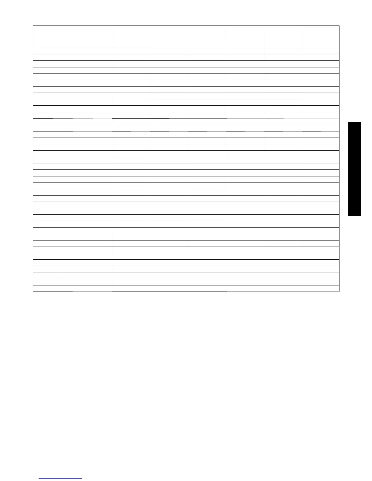
PHYSICAL DATA -- OUTDOOR UNIT 38HDR
Outdoor Unit 38HDR 018 024 030 036 48 60
System Voltage 208/230---1 ---60 208/230---1---60 208/230---1 ---60
208/230---1 ---60
208/230---3 ---60
4 6 0 --- 3 --- 60
208/230---1 ---60
208/230---3 ---60
4 6 0 --- 3 --- 60
208/230---1 ---60
208/230---3 ---60
4 6 0 --- 3 --- 6 0
Nominal Capacity (Btuh) 18000 24000 30000 36000 48000 60000
Operating Weight lb(kg) 166 (75.3) 176 (79.8) 250 (113.4) 250 (113.4) 278 (126.4) 306 (139)
Refrigerant Type R---410A
Metering Device TXV
Unit Factory Charge 6.3 (2.9) 6.5 (3.0) 8.7 (4.0) 8.7 (4.0) 12 (5.5) 12 (5.5)
System Charge (25 ft line) lb (kg) 7.0 (3.2) 7.8 (3.5) 10.1 (4.6) 8.9 (4.0) 12.2 (5.5) 12.5 (5.7)
Additional Charge .7 (.32) 1.3 (.57) 1.4 (.64) .2 (.1) .2 (.1) .5 (.23)
Compressor
Type Scroll
O i l C h a r g e ( P O E --- o z ) 25 25 25 25 42 42
Crankcase Heater --- --- 40 40 40 40
Accumulator Ye s
Outdoor Fan
Rpm/CFM 840/1720 840/1720 840/3900 840/3900 840/3900 840/3900
Diameter (in) .. No. of Blades 18…3 18…3 24…3 24…3 24…3 24…3
Motor HP 1/8 1/8 1/4 1/4 1/4 1/4
Outdoor Coil
Face Area (sq. ft) 5.8 7.3 12.1 12.1 14.1 14.1
No. Rows 2 3 2 2 3 3
Fins per inch 20 20 20 20 20 20
Circuits 2 3 3 6 6 6
High Pressure Switch
C u t --- I n ( p si g ) 420±25 420±25 420±25 420±25 420±25 420±25
C u t --- O u t ( p s ig ) 650±10 650±10 650±10 650±10 650±10 650±10
Low Pressure Switch
C u t --- I n ( p si g ) 45±25 45±25 45±25 45±25 45±25 45±25
C u t --- O u t ( p s ig ) 20±5 20±5 20±5 20±5 20±5 20±5
Fusible Plug ° F (° C) 210 (99)
Refrigerant Lines
Connection Type L i qu i d / S u c t i o n --- S w e a t
Suction/Vapor (in) OD 5/8 3/4 7/8 7/8†
Liquid Line (in) OD 3/8
Maximum Length* ft (m) 200 (61)
MaxLift(FanCoilAbove)ft(m) 65 (20)
Max Dr op (Fan Coil Below) ft (m) 200 (61)
Controls
Control Voltage 24 vac
External Finish Gray
* Refer to Long Line Application
{ Valve size connection is 7/8 inch. Recommended line size is 1---1/8 inch.
40QAC/38HDR -- 40QAQ/38QR
 Loading...