3342 GW
English
Installation
IIMPORTANT:
Do not lift the unit by the condensate drain discharge pipe; hold it
by its four corners only.
Unit installation will be facilitated using a stacker (See g. 16).
If plaster board ceiling panels are installed the maximum dimensions
of the unit housing must not exceed 660 x 660 mm (mod. 200-300-400)
and 900 x 900 mm (mod. 500-600-700).
In rooms with high humidity, brackets should be insulated by self
adhesive insulation supplied.
Installation
Mark the position of the hangers, connection lines and condensate
drain pipe, power supply cables and remote control cable (see
dimensions); the cardboard template (supplied with the kit) may be of
assistance for this operation.
Depending on the type of ceiling the hangers can be xed as shown in
the drawing 17.
Once the threaded hangers have been positioned, do not tighten the
nuts, and insert the washers as shown in the drawing 18.
First position the connection lines , as described in the chapter "Water
connections". Remove the "T" bar in order to facilitate installation
operations (See g. 19).
Carefully lift the unit (without the frame) using the four suspension
brackets (or the four corners), inserting it into the false ceiling.
If the "T" bar cannot be removed the unit may need to be tilted (this
operation may only be carried out with false ceilings with a minimum
height of 300 mm) (See g. 20).
Align and level the unit by adjusting the nuts and locknuts on the
threaded hangers, maintaining a distance of 25 -30 mm between the
sheet metal body and the underside of the false ceiling.
Reposition the "T" bar and align the unit in relation to the bar by
tightening the nuts and locknuts. After the condensate drain pipe and
the water ducts have been connected check, check to make sure that
the unit is level (See g. 21).
Condensate drain pipe
See g. 22 - 23.
• To ensure correct condensate water ow, the drain pipe should have
a gradient of 2% without obstructions. Furthermore an odour trap of
at least 50 mm depth should be made to prevent unpleasant odours
from reaching the room.
• Condensate may be discharged at a maximum height of 200 mm
above the unit, as long as the ascending tube is vertical and aligned
with the drainage ange.
• If it is necessary to discharge the condensate from a level above 200
mm, install an auxiliary water discharge pump and oat valve. A oat
valve is recommended to stop the ow switch if there is a fault at the
auxiliary pump.
• The condensate pipe must be insulated with a condensation-proof
material such as polyurethane, propylene or neoprene of 5 to 10 mm
thickness.
• If more than one unit is installed in the room, the drain system can be
made as shown in the drawing g.23.
Water connections
Checking
On the unit startup, check if water ows correctly from the pump or
check the pipe slope and make sure the pipes are not obstructed.
To make water connections to the heat exchanger or the valves
use threaded joints and suitable materials that can ensure perfect
tightness.
The unit is provided with inlet and outlet female connections for
both 2 and 4 pipe models. An air bleed valve is also provided (See g.
26), which can be adjusted using a 8 mm wrench..
To drain the unit completely, refer to “SYSTEM DRAINAGE” in
the Maintenance section.
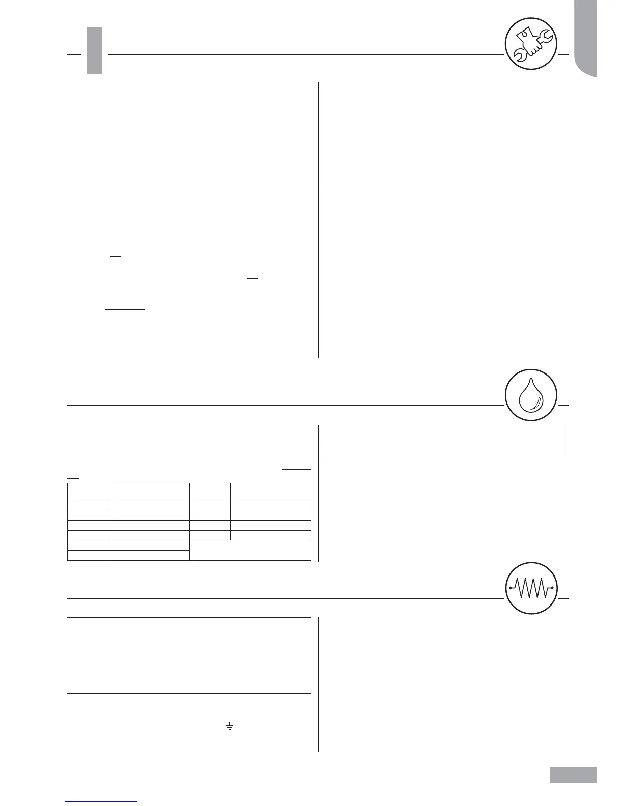
Models
Connections
dimension (Ø)
Models
Connections
dimension (Ø)
200 3/4" 500 1"
300 3/4" 600 1"
400 3/4" 700 1"
200* 1/2" 700 * 3/4"
300* 1/2"
*Hot water circuits, four-pipe
version
400* 1/2"
Electrical connections
IMPORTANT:
• The unit must be installed in compliance with the national standards
on plant installation.
• All cables for connection to the unit, as well as its accessories, must be
H05 VV-F with PCV insulation in compliance with EN 6033-2-40.
• Disconnect all circuits from power supply before acting on energized
components.
• Make earthing before any other electric connections.
In compliance with the installation instructions, the contact opening of
all disconnecting devices (4 mm) must allow full disconnection under
the conditions of overvoltage class III
Connect power supply L (line), N (neutral) and
(earthing) according
to the wiring diagram and respect the polarities shown on the bottom
of the electrical boxes, see g. 36-38-39-40.
All units are equipped with a fuse for machine protection and one for
control protection (type gF 1A).
Refer to table I when replacing the fuse for unit protection.
Control box panels: The control box panel is positioned on the external
side of the unit (g. 1-2). Remove the xing screws and the cover of the
control box panel. The control box panels contain the terminal blocks
for connections as shown in the wiring diagrams and g. 36-38-39-40.

 Loading...