17
CN 23
To C CM
Comm.Bus
X
Y
E
FAN
10
JR6
JR6
Ma gnetism link
0
8
4
1
2
3
5
6
7
C
9
A
B
D
E
F
0~15
32~47
0
8
4
1
2
3
5
6
7
C
9
A
B
D
E
F
0
8
4
1
2
3
5
6
7
C
9
A
B
D
E
F
0
8
4
1
2
3
5
6
7
C
9
A
B
D
E
F
16~31
48~63
Y
C
Notes:
1.To be wire d in acc ordance with Na tional
Electric N.E.C. and lo cal code s.
2.Use C opper c onductors only.
Use con ductors suitable for at le ast 75*C (167*F) .
3. If any of the o riginal wires, as supplie d
must be replace d, use t he sam e or equ ivalent w ire.
Legend:
................Model sp ecic fe ature
CN 1:
CN 17:
CN111 :Comp ressor si gnal
CN 8: Fa n
CN 6: Co nnectors
Live wire L1/Null line L2
Null line C
interface
interface
CN 33: R emote a larm inte rface
CN 23: R emote sw itch interface
CN 13: P ump interface
CN 14: S wing motor interface
CN 5: Wa ter level switch in terface
CN 10: D isplay bo ard inter face
CN 3: Ce ntralized control system Interface
P 1 :Mag netism li nk interfa ce
CN 15: M otor interface
T1: Room tempera ture sen sor
T2: Pipe tempera ture sen sor
XT1:3 po le terminal block
XT 2: 5 p ole term inal bloc k
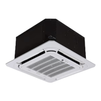
Fig. 35 -- 40MKCB**C wiring diagram
C
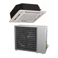
OUTDOOR UNIT SCHEMATIC DIAGRAM
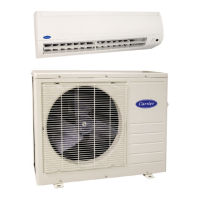
Fig. 36 -- 24AHA4/124ANS Wiring Diagram
 Loading...