15
*Must be enlarged from 1
1
/
8
in. to 1
3
/
4
inches.
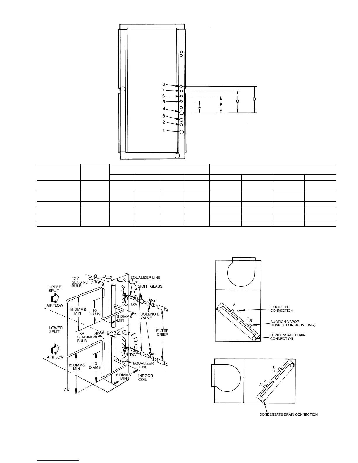
NOTE: Access hole knockouts 1-4 are factory-supplied.
Fig. 6 — Refrigerant and Chilled Water Piping Access Holes
UNIT
USE HOLE
NUMBERS
FIELD-FABRICATED HOLE DIAMETERS,
in. (mm)
FIELD-FABRICATED HOLE POSITION
DIMENSIONS, in. (mm)
No.5No.6No.7No.8ABCD
40RM007,008
40RMQ008
1, 3 — — — — — — — —
40RM012-034
40RMQ012
1, 2, 3, 4 — — — — — — — —
40RMS008-012 4, 5 1
3
/
4
(44.5) — — — 6.25 (158.8) — — —
40RMS014-024 4, 5, 6, 7 1
3
/
4
(44.5) 1
3
/
4
(44.5) 1
3
/
4
(44.5) — 3.0 (76.2) 6.0 (152.4) 10.5 (266.7) —
40RMQ016,024,028 3*, 5, 6, 7 1
1
/
8
(28.6) 1
1
/
8
(28.6) 1
3
/
4
(44.5) — 3.25 (82.6) 6.125 (155.6) 10.38 (263.7) —
40RMS028,034 5, 6, 7, 8 2
1
/
2
(63.5) 2
1
/
2
(63.5) 2
1
/
2
(63.5) 2
1
/
2
(63.5) 6.0 (152.4) 9.625 (244.5) 13.38 (339.9) 17.0 (431.8)
LEGEND
TXV — Thermostatic Expansion Valve
NOTE: Component location arrangement shown for field installation of
sight glasses, solenoid valves, filter driers, and TXV sensing bulbs. The
TXVs and equalizer lines are factory installed.
Fig. 7 — Face-Split Coil Suction and
Liquid Line Piping (Typical)
FIRST ON/LAST OFF = B
VERTICAL INSTALLATION
FIRST ON/LAST OFF = A
HORIZONTAL INSTALLATION
Fig. 8 — Typical Evaporator Coil Connections
(40RM, 40RMQ)



 To Next Page