5
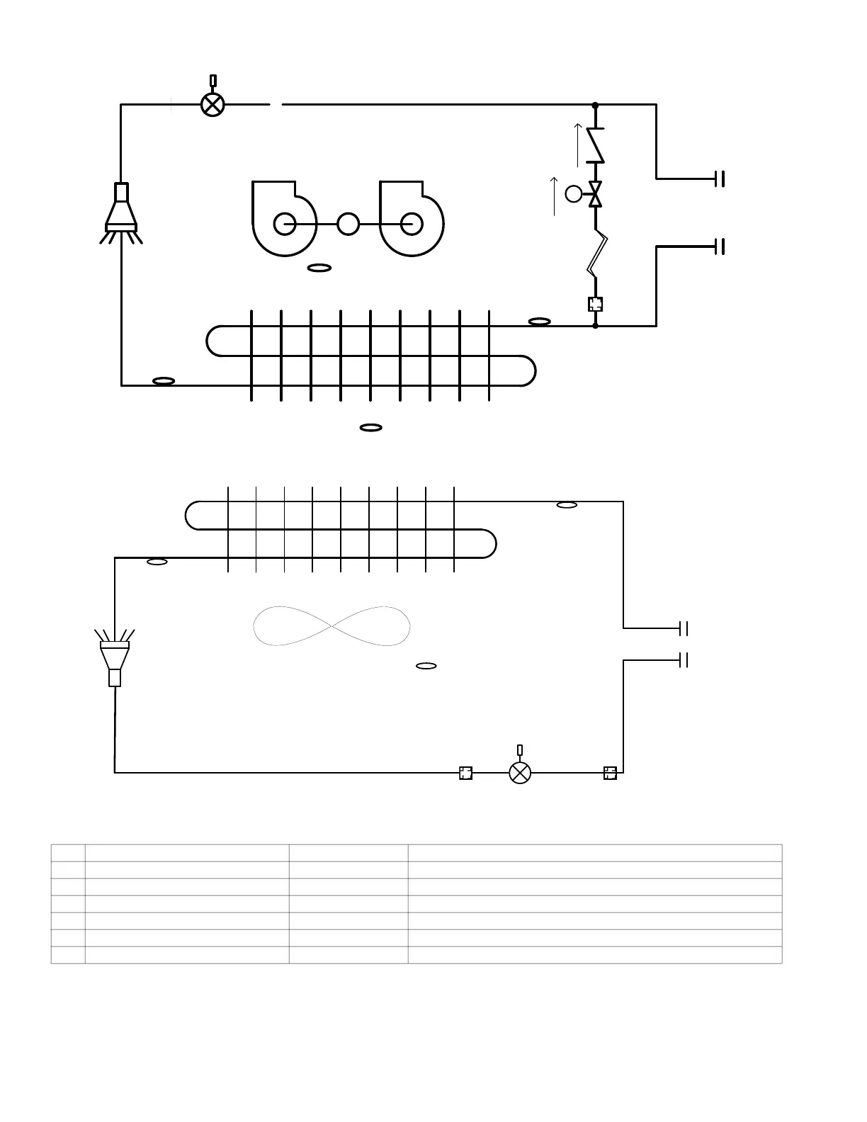
Refrigerant Circuit
Fig. 13 — Refrigerant Circuit Schematic Diagrams for Indoor Units (40VMA)
Fig. 14 —Refrigerant Circuit Schematic Diagrams for Indoor Units (40VMC, F, H, I, L, M, R, U, V, W)
Table 2 —Refrigerant Circuit Component Function
NO. NAME SYMBOL FUNCTION
1 Room or return air temperature sensor T1 (T0 for 40VMA) Used for thermostat control
2 Inlet pipe temperature sensor T2A Used to calculate subcooling (SC) when heating
3 Outlet pipe temperature sensor T2B Used to calculate superheated (SH) when cooling
4 Electronic expansion valve EEV Used to control SH in cooling and SC in heating
5 Room temperature sensor TA (Only for 40VMA) Used to stabilize outlet air temperature by controlling fan speed or EEV opening
6 Solenoid valve SVD (Only for 40VMA) Used to prevent refrigerant trapping in the heat exchanger
0
)DQ
3LSLQJ
*DVVLGH
3LSLQJ
/LTXLGVLGH
&KHFNYDOYH
&DSLOODU\WXEH
)DQ
*DVVLGH3LSLQJ
/LTXLGVLGH3LSLQJ
 Loading...